Pattern generator using a dual phase step element and method of using same

Inactive Publication Date: 2006-05-25
ASML HLDG NV
View PDF27 Cites 17 Cited by
  • Summary
  • Abstract
  • Description
  • Claims
  • Application Information

AI Technical Summary

Benefits of technology

[0011] According to one embodiment of the present invention, there is provided a patterning device comprising an array of first reflecting components, an array of second reflecting components, and an array of controllers. Each of the first reflective components has a first width and a first length. Respective ones of the array of second reflective components are coupled to a central portion of respective ones of the array of first reflective components. Each of the second reflective components has a second width, which is substantially equal to the first width, and

Problems solved by technology

When imaging with tilting mirrors, there can be a telecentricity error.
However, because of intensity modulation constraints (e.g., unequal maximum amplitude of positive and negative light) these arrays cannot effectively emulate phase shifting masks and/or are inefficient when correcting telecentric errors.
This increases sensitivity (e.g., speed), but can sacrifice resolution.
There are, however, as discussed above, limi

Method used


Image

  • Pattern generator using a dual phase step element and method of using same
  • Pattern generator using a dual phase step element and method of using same
  • Pattern generator using a dual phase step element and method of using same

Examples


Embodiment Construction

Overview

[0023] Although specific reference may be made in this text to the use of a patterning device in a lithographic system that patterns a substrate, it should be understood that the patterning device described herein may have other applications, such as in a projector or a projection system to pattern an object or display device (e.g., in a projection television system, or the like). Therefore, the use of the lithographic system and / or substrate throughout this description is only to describe example embodiments of the present invention.

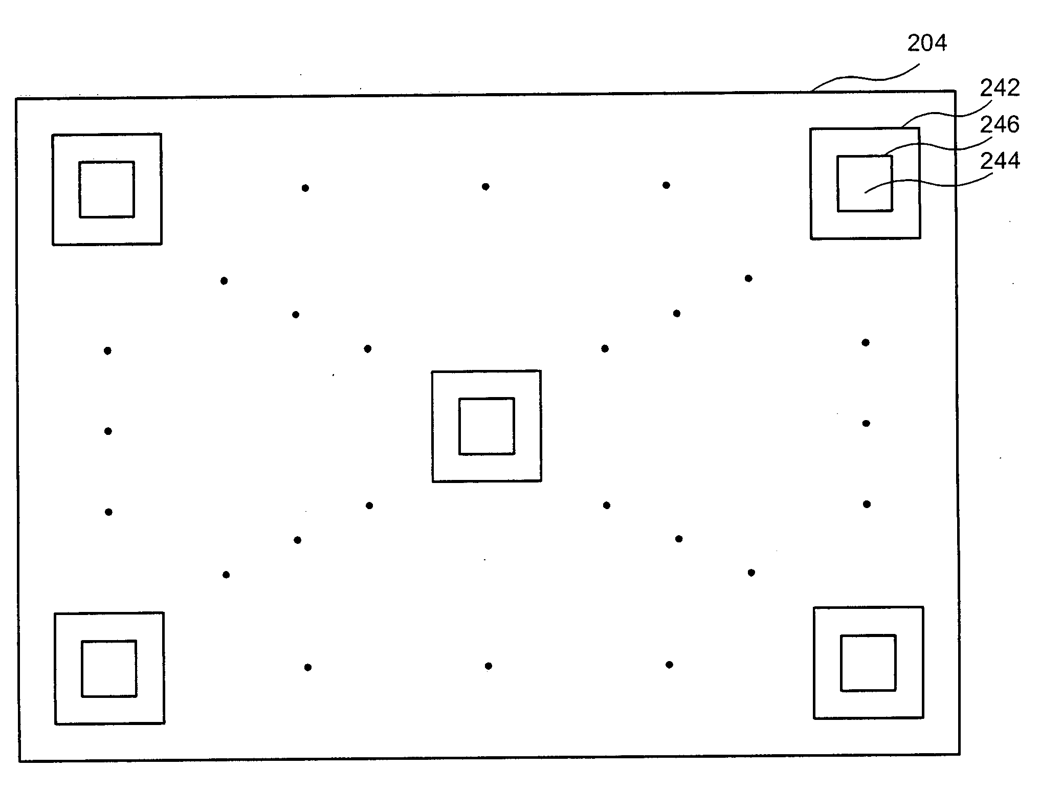
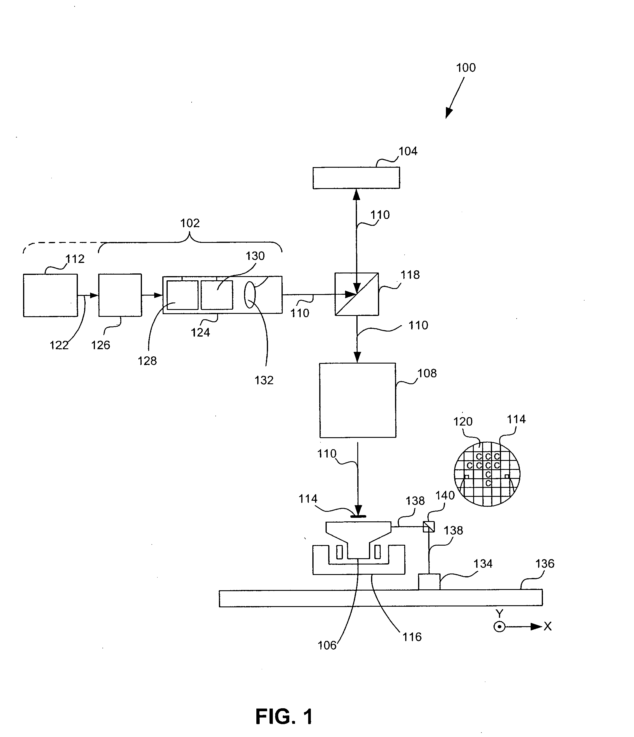
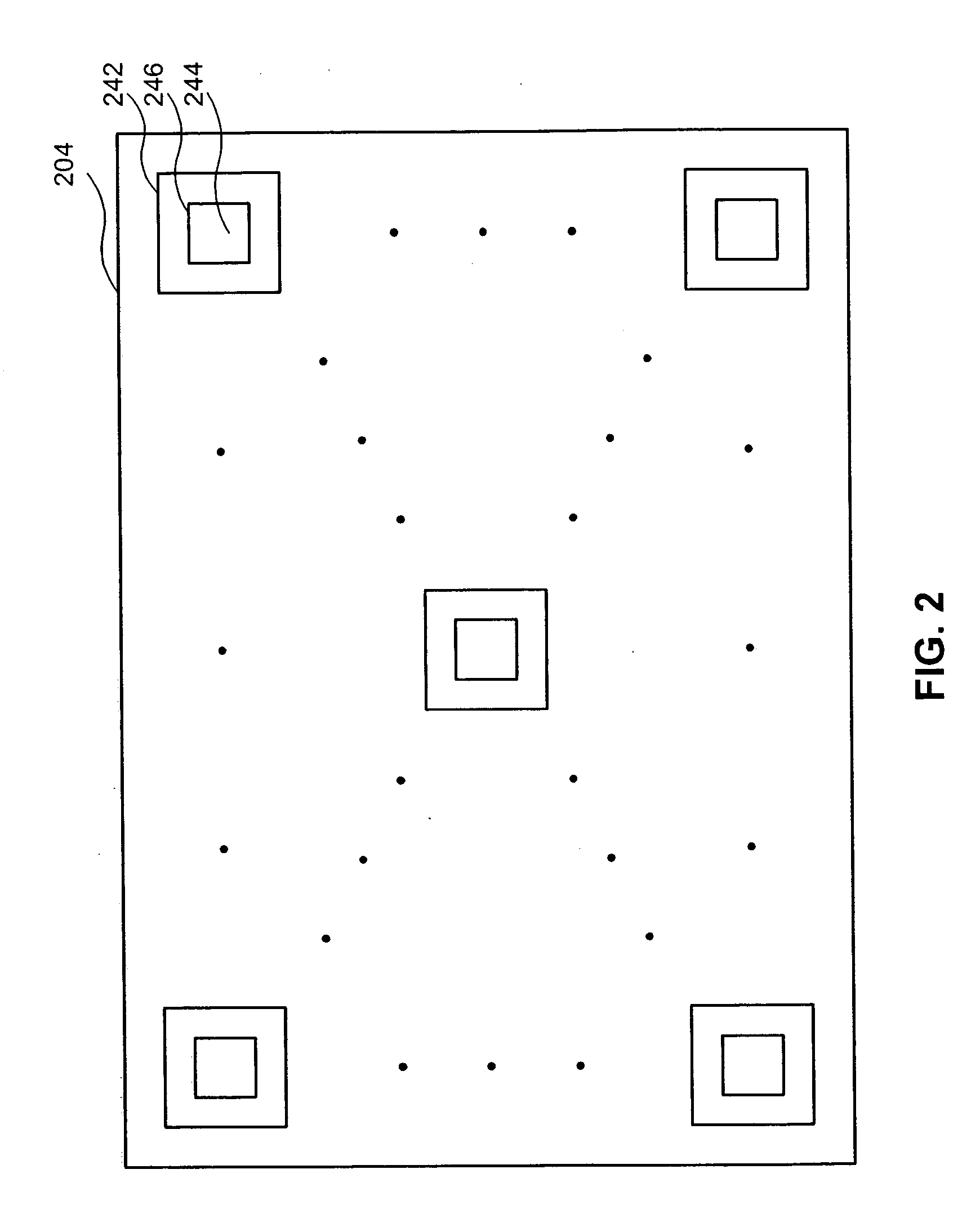
[0024] A system and method are used to pattern light using an illumination system, an array of individually controllable devices, and a projection system. The illumination system supplies a beam of radiation. The array of individually controllable elements patterns the beam. The array of individually controllable elements comprises mirrors having first and second steps on opposite edges. The projection system projects the patterned beam onto ...


PUM


Abstract

A system and method are used to pattern light using an illumination system, an array of individually controllable components, and a projection system. The illumination system supplies a beam of radiation. The array of individually controllable elements patterns the beam. The array of individually controllable elements comprises mirrors having first and second steps on opposite edges. The projection system projects the patterned beam onto a target portion of an object. In various examples, the object can be a display, a semiconductor substrate or wafer, a flat panel display glass substrate, or the like, as is discussed in more detail below.

Description

BACKGROUND [0001] 1. Field of the Invention [0002] The present invention relates to a light patterning device and method of using same. [0003] 2. Related Art [0004] A patterning device is used to pattern incoming light. A static patterning device can include reticles or masks. A dynamic patterning device can include an array of individually controllable elements that generate a pattern through receipt of analog or digital signals. Example environments for use of the patterning device can be, but are not limited to, a lithographic apparatus, a projector, a projection display apparatus, or the like. [0005] When imaging with micromirror arrays as the object, the phase of the light reflected by each mirror is critical. For example, when a flat tilting mirror is untilted (e.g., resting) light at the image plane and / or collected at projection optics is considered to have on average zero phase, i.e., has positive amplitude. During tilting of the mirror, there is an tilt angle at which no l...

Claims


Application Information

Patent Timeline
IPC IPC(8): G02B6/26
CPCG02B26/0833G03F7/70283G03F7/70291
Inventor BABA-ALI, NABILA
Owner ASML HLDG NV
Why Eureka
Try Eureka