Urine collection apparatus

a technology for collecting apparatuses and urine, applied in medical science, non-surgical orthopedic devices, packaging, etc., can solve problems such as difficulty in urinating without assistance and urination may be problemati

Inactive Publication Date: 2006-05-25
ONKOLOGIE INTERNASIONALE BELEGGINGS
View PDF4 Cites 15 Cited by
  • Summary
  • Abstract
  • Description
  • Claims
  • Application Information

AI Technical Summary

Benefits of technology

The technical effect of this patent is that it describes a device called a urine receptacle that can receive both air and urine from another system. It also has an outlet for air that can be connected to a vacuum or other low-pressure source. This allows for efficient collection and disposal of urine without causing blockages or fluctuations in pressure.

Problems solved by technology

The technical problem addressed by this patent is how to help bedridden patients who are unable to control their bladders or have difficulty with urinating to easily collect urine without assistance.

Method used


Image

  • Urine collection apparatus
  • Urine collection apparatus
  • Urine collection apparatus

Examples


Embodiment Construction

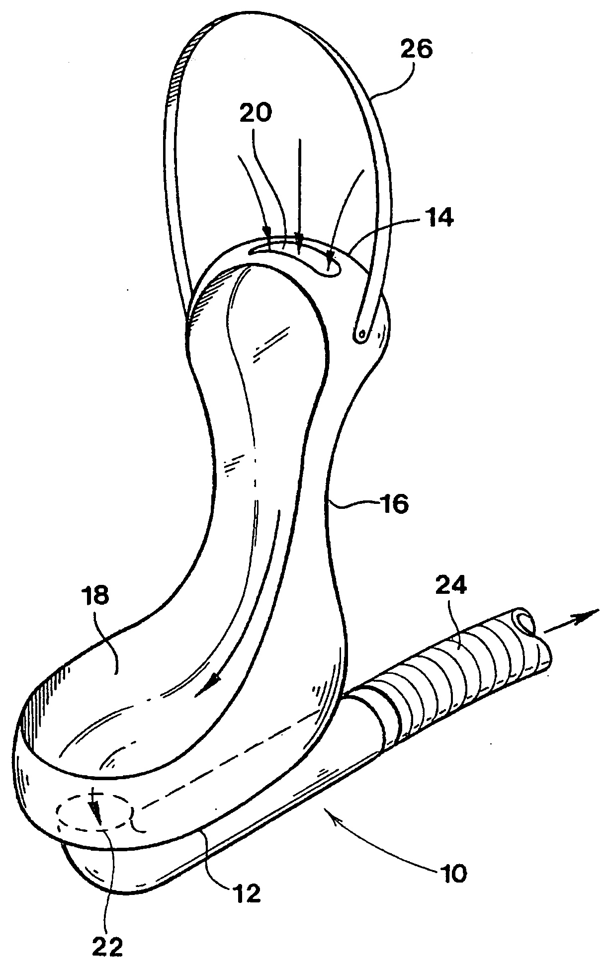
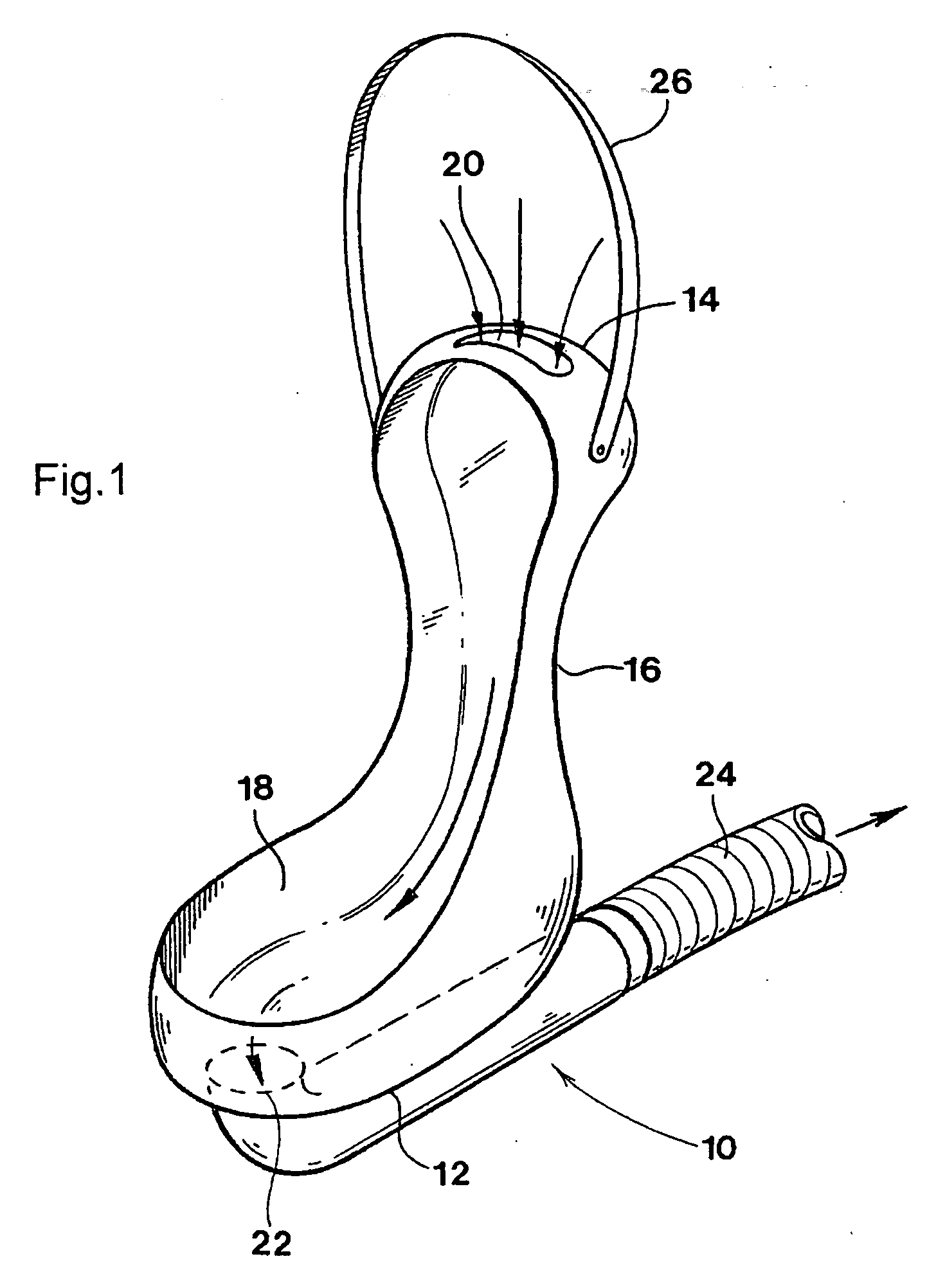
[0021]FIG. 1 shows a urine collector of the invention which comprises a hollow body 10 having enlarged opposed ends 12 and 14 and a narrowed central region 16. The ends are smoothly rounded. The collector is curved as shown and defines an opening 18 on its inner side which is shaped, together with the curvature of the body of the collector, to fit snugly against the perineal region of a female patient. In order to accommodate different patients, the collector body can conveniently be moulded from a flexible plastics material, and should ideally be disposable.

[0022] An air inlet 20 is formed in the first end 14 of the collector, and an outlet 22 for air and urine, which can be connected to a flexible hose or pipe 24, is formed at the other end 12. When the collector is placed against the body of a patient, air flowing into the inlet 20 and out of the outlet 22 entrains urine and carries it away for separation from the air.

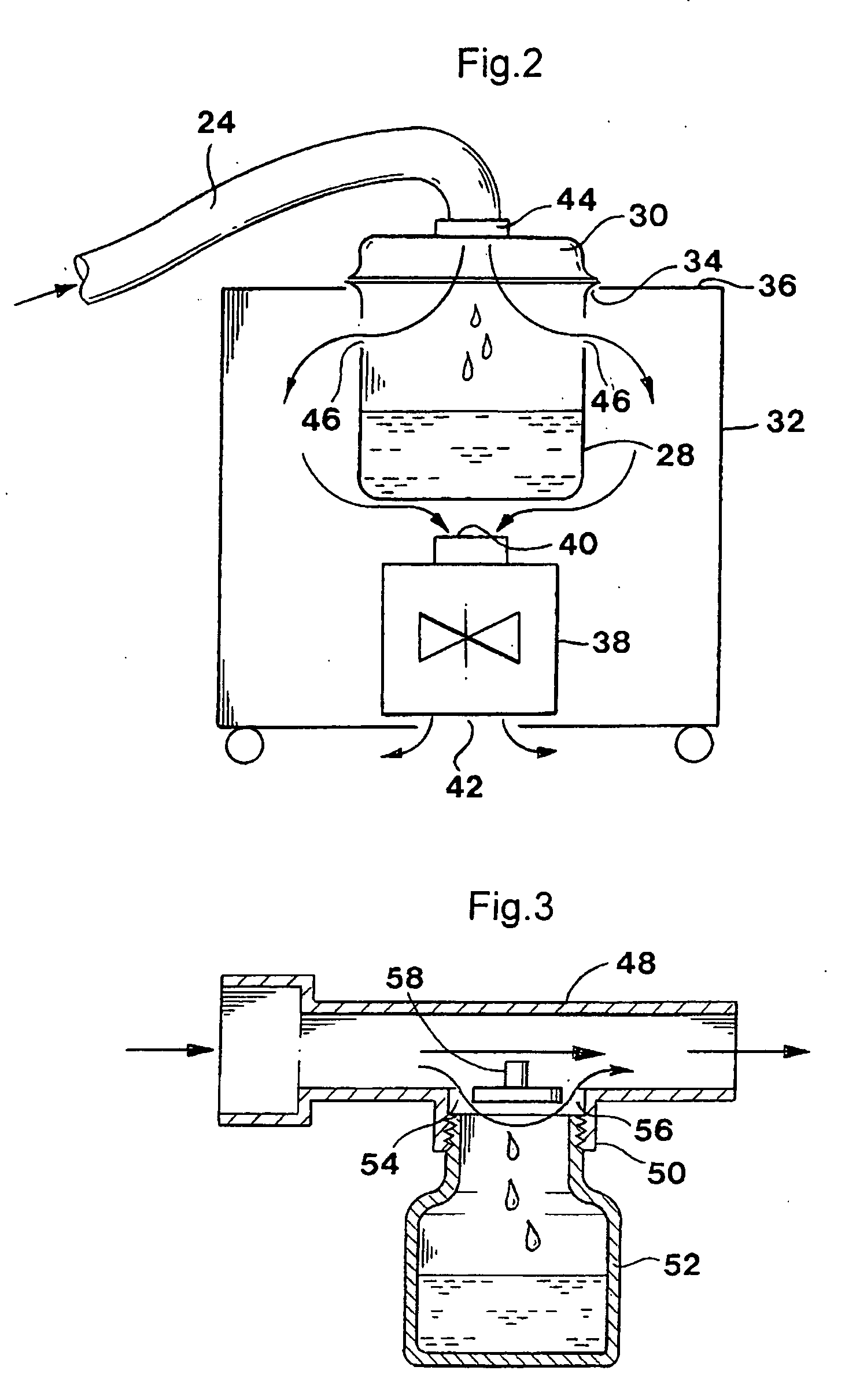
[0023] In order to enhance the efficiency of urine collectio...


PUM


Abstract

Urine collection apparatus is provided which can be used to assist bedridden and/or incontinent patients, particularly female patients. The apparatus includes a urine collector which is shaped for location against the perineal region of a patient adjacent the urethra. The urine collector comprises a hollow body having opposed ends in which an inlet for air and an outlet for air and urine are formed, respectively. The body has a central region between the end regions with a reduced cross-sectional area. This effectively creates a venturi adjacent the patient's urethra when air passes through the collector. The apparatus includes a urine receptacle with an inlet for receiving air and urine from the collector, and an outlet for air which is connectable to a source of low pressure. The source of low pressure will typically be an impeller driven by an electric motor, which creates a sufficiently strong air flow through the apparatus to entrain urine and transport it to the receptacle.

Description


Claims


Application Information

Patent Timeline
Owner ONKOLOGIE INTERNASIONALE BELEGGINGS
Why Eureka
Try Eureka