Self watering plant receptacle

Inactive Publication Date: 2006-06-01
VOGT PAUL
View PDF22 Cites 19 Cited by
  • Summary
  • Abstract
  • Description
  • Claims
  • Application Information

AI Technical Summary

Benefits of technology

[0008] According to the present invention, a self watering plant receptacle which can sustain the life of a plant for several days between tending is provided, that comprises a container consisting of several compatible portions, an upper portion which acts to hold soil and capture an absorptive matter portion which projects through its base, while an attachable lower portion would act as an enclosed water reservoir that when mated would yield a gap of sort for refilling the established water reservoir.
[0009] The absorptive matter portion of the present invention can be of a cotton type rope, sponge, compressed particle, woven material, or other absorbent substance that would draw water up from an attached lower water reservoir portion to replenish the upper soil containment portion in turn providing a plant with a steady supply of moisture for a lengthy period of time.

Problems solved by technology

While potted plants are virtually in every home and business throughout the world, they often times present quite a challenge seeing the vast majority of contained plants need constant tending.
This holds true mainly because these minimal growing environs cannot sustain an adequate supply of water for an extended period of time.
Applicant is also aware of other plant containers that have introduced water catch basins or bowls in an attempt to capture more moisture, but all rely on a plants roots to invade such areas which inevitably put a plant's livelihood in jeopardy due to several funguses which can incur, as can such designs starve a plants soil area of oxygen due to over saturation.

Method used


Image

  • Self watering plant receptacle
  • Self watering plant receptacle
  • Self watering plant receptacle

Examples


embodiment 9

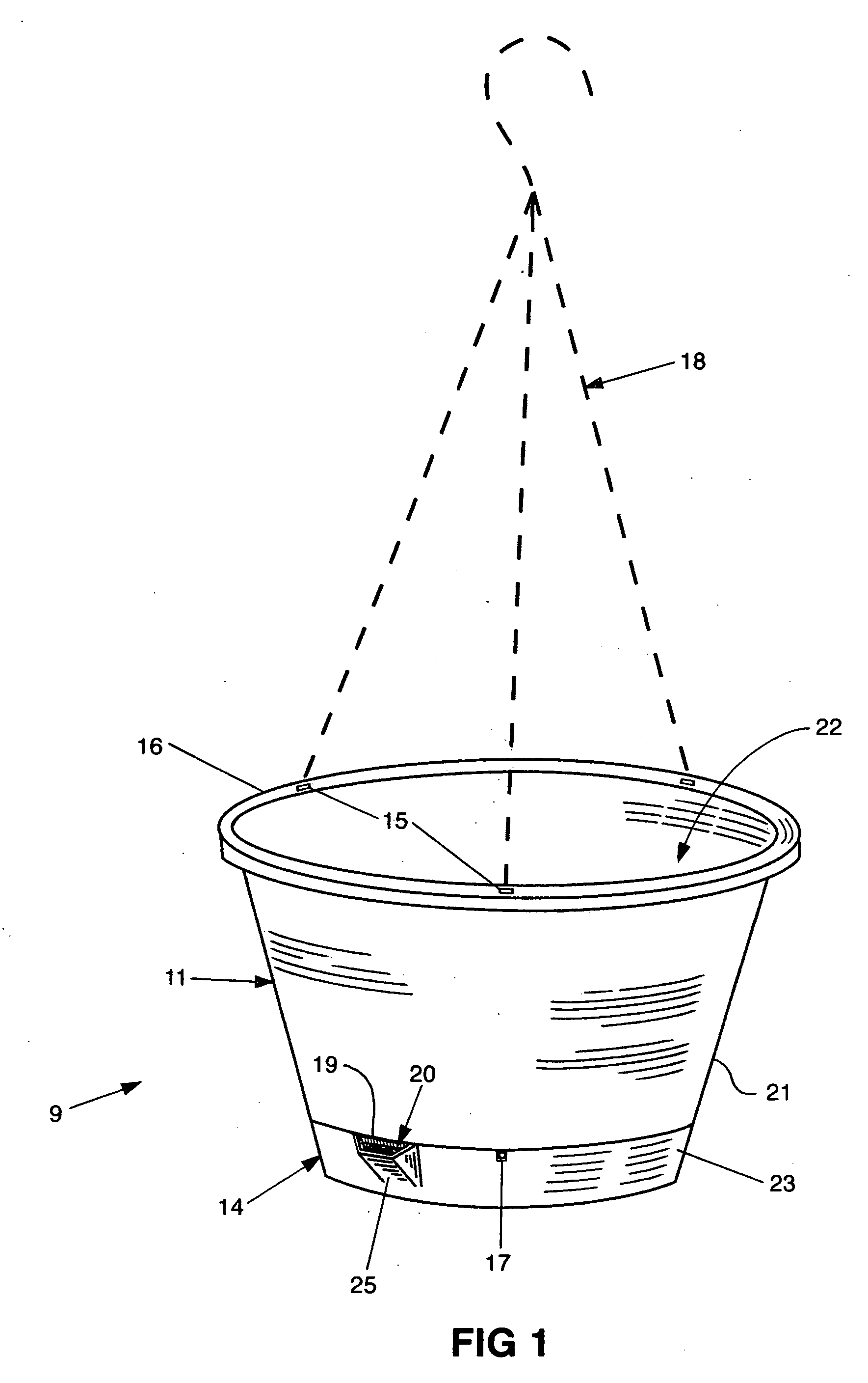
[0024] Ultimately extracting stored water from the reservoir portion 14, and dispersing the water upwardly into the soil portion 11 is accomplished by another piece of the assembly known to be an absorptive matter portion 12, resembling a cord or a rope as shown in FIG. 2, although it should be recognized the absorptive matter portion 12 may be of sponge or another suitable substance (reference FIG. 5) capable of wicking water and conformable for implementation into assembly of embodiment 9.

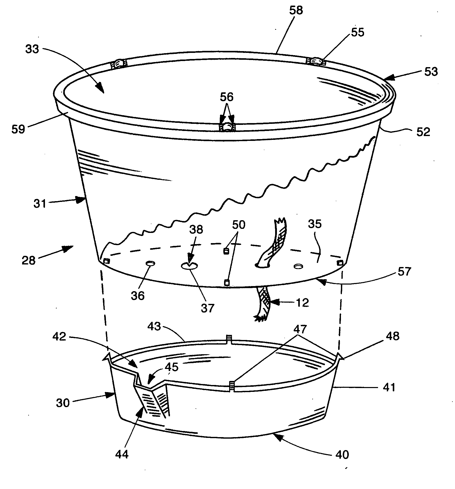
[0025] With further attention directed to FIG. 2, another preferred embodiment or receptacle 28 similar to that of FIG. 1 is shown, revealing on absorptive matter portion 12 captured in the base area 35 of the upper soil portion 31. Openings 37 having an inwardly projecting prong 38 or serrated edge of sort, would act to restrain the absorptive matter portion 12 at a midway point of its overall length, insuring moisture absorption from any depth within the water reservoir portion 30, and appropri...

embodiment 28

[0029] Once coupled, the sidewall 52 of the soil portion 31 would be flush or slightly stepped outward from the sidewall 41 of the reservoir portion 30, allowing the open recess 45 created by the cupped protrusion 44 on the reservoir 30 to protrude outwardly from the embodiment 28 permitting water to be administered into the reservoir portion 30, exclusively.

[0030] In the base 35 of the soil portion 31, small holes 36 may also be implemented to increase oxygen supply to the soil contained in the created basin 33.

[0031] The soil portion 31 includes a rim 53 which juts outwardly from the top of the sidewall 52 and includes indentations 55 having one or more cavities 56 for optional hanger 18 attachment. The indentations 55 residing on the top surface 58 of the rim 53, could accordingly be situated on the outer edge 59 of the rim 53, and may or may not include cavity 56.

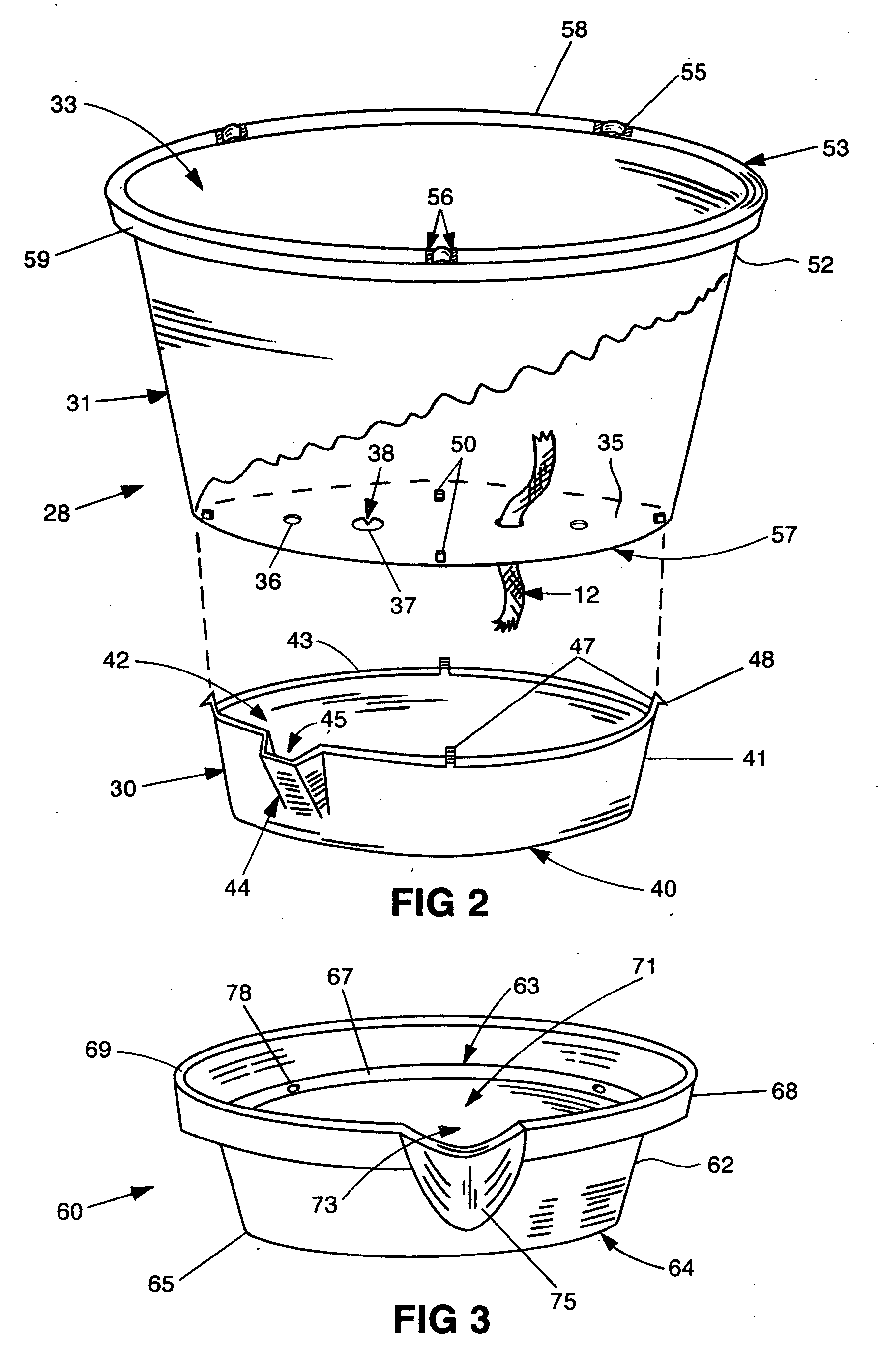
[0032] With further attention directed to FIG. 3, an optional water reservoir portion 60 is shown, wherein the lowe...


PUM


Abstract

A plant receptacle comprised of several compatible portions which work in unison to readily supply water as needed to a plant for several days. An upper portion of designed plant container would act to hold soil and contain an absorptive matter portion, which would protrude from its base area, and would act to wick water from a connectable lower portion which would act to encapsulate a volume of water, and when mated, a gap of sort is thus formed for refilling the created water reservoir.

Description

BACKGROUND OF THE INVENTION [0001] The invention at hand is relative to plants which are restrained to a limited growing environment, in essence, to a distinct self watering plant receptacle which could sustain life to a wide variety of plants from multiple origins for an extended period of time without daily human assistance. [0002] While potted plants are virtually in every home and business throughout the world, they often times present quite a challenge seeing the vast majority of contained plants need constant tending. This holds true mainly because these minimal growing environs cannot sustain an adequate supply of water for an extended period of time. [0003] Although a variety of plant containers have been developed over the years, they have predominantly relied on the soil capacity as a means for water saturation (content). [0004] Applicant is also aware of other plant containers that have introduced water catch basins or bowls in an attempt to capture more moisture, but all...

Claims


Application Information

Patent Timeline
IPC IPC(8): A01G25/00
CPCA01G27/04
Inventor VOGT, PAUL
Owner VOGT PAUL
Why Eureka
Try Eureka