Wellbore pump

a wellbore pump and wellbore technology, applied in the direction of positive displacement liquid engine, fluid removal, borehole/well accessories, etc., can solve the problems of complicated use of pumping equipment in the case of wells under pressure, and dangerous problems

Inactive Publication Date: 2006-06-01
NATURAL ELEVATOR SYST
View PDF6 Cites 37 Cited by
  • Summary
  • Abstract
  • Description
  • Claims
  • Application Information

AI Technical Summary

Benefits of technology

[0011] The valve is biased in the open position by a piston and a spring mechanism of selected strength and force, the spring being held in cylinder chamber isolated by the piston sealed against the inner diameter of said cylinder. The spring is selected such that its force is overcome by a selected hydrostatic pressure acting on the opposite side of the piston which is achieved when fluids in the well reach a certain hydrostatic head. When the valve is closed it prevents further flow through the plunger causing the reservoir pressure to build up beneath the plunger and forcing it to the surface and causing the liquid in front of it to be pumped to the surface and out of the well.

Problems solved by technology

The foregoing method, however, involves workers′ time and attention at periodic intervals and the use of pumping equipment which in the case of the well under pressure can be complicated, as well as dangerous.

Method used


Image

  • Wellbore pump
  • Wellbore pump
  • Wellbore pump

Examples


Embodiment Construction

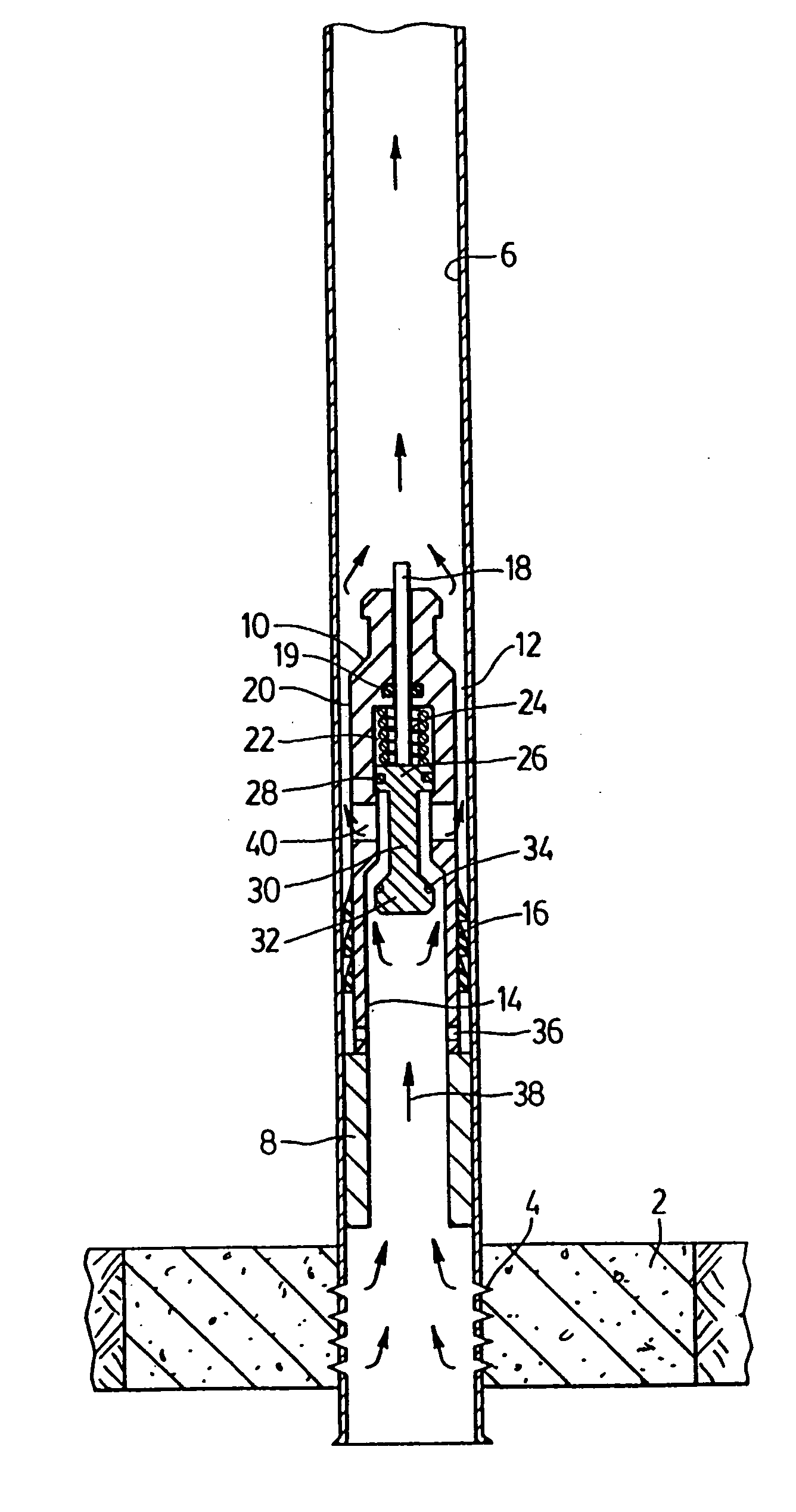
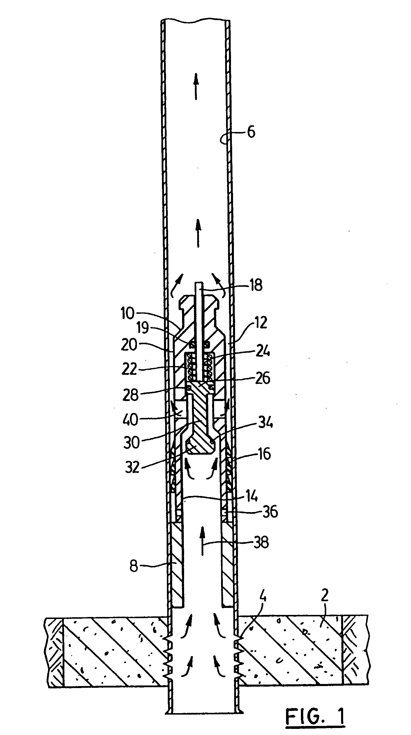
[0022] In the illustrated embodiment of FIG. 1 a natural gas reservoir 2 is producing natural gas through perforations 4 into the wellbore 6 which is a string of hollow pipe extending to the well head at the surface.

[0023] Above the reservoir formation is a collar 8 mounted in the wellbore at a fixed location and presenting a hollow centre with a reduced internal diameter.

[0024] Resting on top of the collar is a plunger 10 of the elongated generally cylindrical configuration of smaller diameter than the wellbore so as to provide an annular gap or space 12 between the plunger and the internal surface of the wellbore 6.

[0025] The plunger has a lower end 14 with a substantially hollow core and having seals 16 mounted on the outer surface thereof capable of forming a seal between the plunger and the inner surface of the wellbore.

[0026] The upper end 20 of the plunger 10 has a cylinder chamber 22 housing a spring 24 which extends between the upper end of the chamber and the chamber e...


PUM


Abstract

The wellbore pump of the present invention comprises a plunger having passage means which may be open or closed by a valve operated by a piston which is biased in the open position by a spring of selected strength such that the wellbore pressure may overcome the spring to close the valve when the accumulated hydrostatic pressure reaches a certain value. When the valve closes the reservoir pressure forces the plunger to the surface and causes the accumulated liquids to be pumped out of the wellbore. A stem extending from the top of the piston engages a top plate and causes the valve to open when the plunger reaches the top of the wellbore. Means is provided whereby the valve opens when it reaches the top of the wellbore and a latch may be provided to retain the plunger from returning to the bottom of the well.

Description

CROSS-REFERENCE TO RELATED APPLICATIONS [0001] This is a Divisional Application of U.S. Ser. No. 10 / 334,920 filed Dec. 31, 2002.BACKGROUND OF THE INVENTION [0002] This invention relates to apparatus for the improved production of oil and natural gas wells. In particular, it relates to a mechanism which will automatically discharge accumulated liquids from the wellbore, without external force or energy. [0003] Natural gas wells, unlike some oil wells, because of gases light weight and the capacity to expand when pressure is relieved, are able to flow naturally as a result of reservoir pressure without the need to be pumped as is the case in low pressure oil wells. [0004] This phenomena is, however, subject to the exception that associated fluids in the nature of liquid such as water, oil, or petroleum condensates, tend to accumulate in the wellbore and when they reach a certain volume or hydrostatic head in the wellbore create a back pressure which is enough to diminish the flow of n...

Claims


Application Information

Patent Timeline
Patent Type & Authority Applications(United States)
IPC IPC(8): E21B43/00E21B43/12F04B47/12
CPCE21B43/121F04B47/12
Inventor LEE, DAN
Owner NATURAL ELEVATOR SYST
Why Eureka
Try Eureka