Degradable material assisted diversion or isolation

a technology of degradable materials and diversion or isolation, which is applied in the direction of fluid removal, borehole/well accessories, chemistry apparatus and processes, etc., can solve the problems of fractures not completely closing, and inability to completely close the fractur

Active Publication Date: 2006-06-01
SCHLUMBERGER TECH CORP
View PDF12 Cites 232 Cited by
  • Summary
  • Abstract
  • Description
  • Claims
  • Application Information

AI Technical Summary

Benefits of technology

[0016] Other aspects and advantages of the invention will become evident from the following description and the accompanying claims.

Problems solved by technology

For a variety of reasons, such as inherently low permeability of the reservoirs or damage to the formation caused by drilling and completion of the well, the flow of hydrocarbons into the well is undesirably low.
In “acid” fracturing, the second fluid contains an acid or other chemical such as a chelating agent that can dissolve part of the rock, causing irregular etching of the fracture face and removal of some of the mineral matter, resulting in the fracture not completely closing when the pumping is stopped.
However, this approach is extremely costly.
The costs come from extensive wireline service intervention, which requires additional time to perforate and to set and then retrieve the packer from the wellbore for each pay zone before and after a fracturing treatment.
In addition, packer retrieval is sometimes risky.
First, it considerably reduces the shut-in time by flowing each fracture back early.
The main disadvantage is the cost and time needed to set the plug.
However, due to initial in-situ stress variations, not all zones may be fractured.
Furthermore, the proppant placement requires loading the wellbore with proppant, which may result in low efficiency of the treatment.
Acquiring reliable pressure data involves testing each zone, adding time and cost to the completion.
Without knowing the exact data, a treatment may result in little or no production from some sets of perforations.
In some cases, the presence of such ball sealers in the wellbore after the treatment presents operational problems during their retrieval.
This makes ISDT not easily repeatable in areas with varying properties.
As a result, currently there is no reliable methodology to justify the use of ISDT in tight gas reservoirs.

Method used


Image

  • Degradable material assisted diversion or isolation
  • Degradable material assisted diversion or isolation
  • Degradable material assisted diversion or isolation

Examples


Embodiment Construction

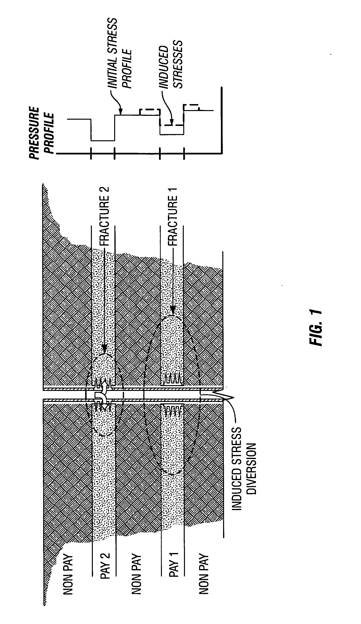
[0013] A method for well treatment by forming a temporary plug in a fracture, a perforation, or a wellbore (or more than one of these locations) penetrating a subterranean formation is provided. A method of well treatment in accordance with one embodiment of the invention includes: injecting a slurry comprising a degradable material, allowing the degradable material to form a plug in a perforation, a fracture, or a wellbore penetrating a formation; performing a downhole operation; and allowing the degradable material to at least partially degrade after a selected duration such that the plug disappears. The degradable materials may be a polymer or co-polymer of esters, amides, or other materials. The degradable material degrades after a selected duration under the downhole conditions such that no additional intervention is needed to remove the plug.

[0014] The temporary blockage by plug formation allows other well operations to be performed without damaging the existing fracture or w...


PUM


Abstract

A method for well treatment by forming a temporary plug in a fracture, a perforation, a wellbore, or more than one of these locations, in a well penetrating a subterranean formation is provided, in which the method of well treatment includes: injecting a slurry comprising a degradable material, allowing the degradable material to form a plug in a perforation, a fracture, or a wellbore in a well penetrating a formation; performing a downhole operation; and allowing the degradable material to degrade after a selected time such that the plug disappears.

Description

BACKGROUND OF THE INVENTION [0001] This application is a Continuation-in-Part of U.S. patent application Ser. No. 11 / 156,966, entitled “Degradable Fiber Systems For Stimulation,” filed Jun. 20, 2005, hereby incorporated in its entirety. This application is also a Continuation-in-Part of U.S. patent application Ser. No. 11 / 206,898, entitled “Methods For Controlling Fluid Loss,” filed Aug. 18, 2005, hereby incorporated in its entirety, which claimed the benefit of U.S. Provisional Application 60 / 606,270, filed Sep. 1, 2004. The invention relates to stimulation of wells penetrating subterranean formations. More particularly, it relates to fracturing and post-job protection of hydraulic fractures.[0002] Hydrocarbons (oil, condensate, and gas) are typically produced from wells that are drilled into the formations containing them. For a variety of reasons, such as inherently low permeability of the reservoirs or damage to the formation caused by drilling and completion of the well, the fl...

Claims


Application Information

Patent Timeline
Patent Type & Authority Applications(United States)
IPC IPC(8): E21B43/267
CPCC09K8/42C09K8/467C09K8/508C09K8/68C09K8/76C09K8/80E21B43/26
Inventor WILLBERG, DEANBULOVA, MARINAFREDD, CHRISTOPHER N.VOSTRUKHOV, ALEXEYBONEY, CURTIS L.LASSEK, JOHNHOEFER, ANN M.W.SULLIVAN, PHILIP F.
Owner SCHLUMBERGER TECH CORP
Why Eureka
Try Eureka