Vehicle seat side air bag system

a technology for side air bags and vehicle seats, which is applied in the direction of vehicular safety arrangements, pedestrian/occupant safety arrangements, vehicle components, etc., can solve the problems of air bag deployment time, air bag and increased air bag deployment time. , to achieve the effect of resisting elastic deformation of trim covers

Inactive Publication Date: 2006-06-01
LEAR CORP
View PDF14 Cites 48 Cited by
  • Summary
  • Abstract
  • Description
  • Claims
  • Application Information

AI Technical Summary

Benefits of technology

[0008] According to one aspect of the present invention, a vehicle seat assembly is provided that comprises a frame and a pad formed of a shaped structural foam material. The pad defines a pocket for receiving an air bag restraint sub-assembly that is assembled to the frame. The restraint sub-assembly has a housing in which an air bag and an inflator are received. The housing has a split line that functions as a stress riser in a wall of the housing. Upon inflation of the air bag by the inflator, the air bag is deployed through the split line. A trim cover is assembled to the pad and subs

Problems solved by technology

The softness and elasticity of covering materials and urethane foam padding present problems for air bag deployment.
This may increase air bag deployment time and result in variability in air bag deployment location.
T

Method used


Image

  • Vehicle seat side air bag system
  • Vehicle seat side air bag system
  • Vehicle seat side air bag system

Examples


Embodiment Construction

)

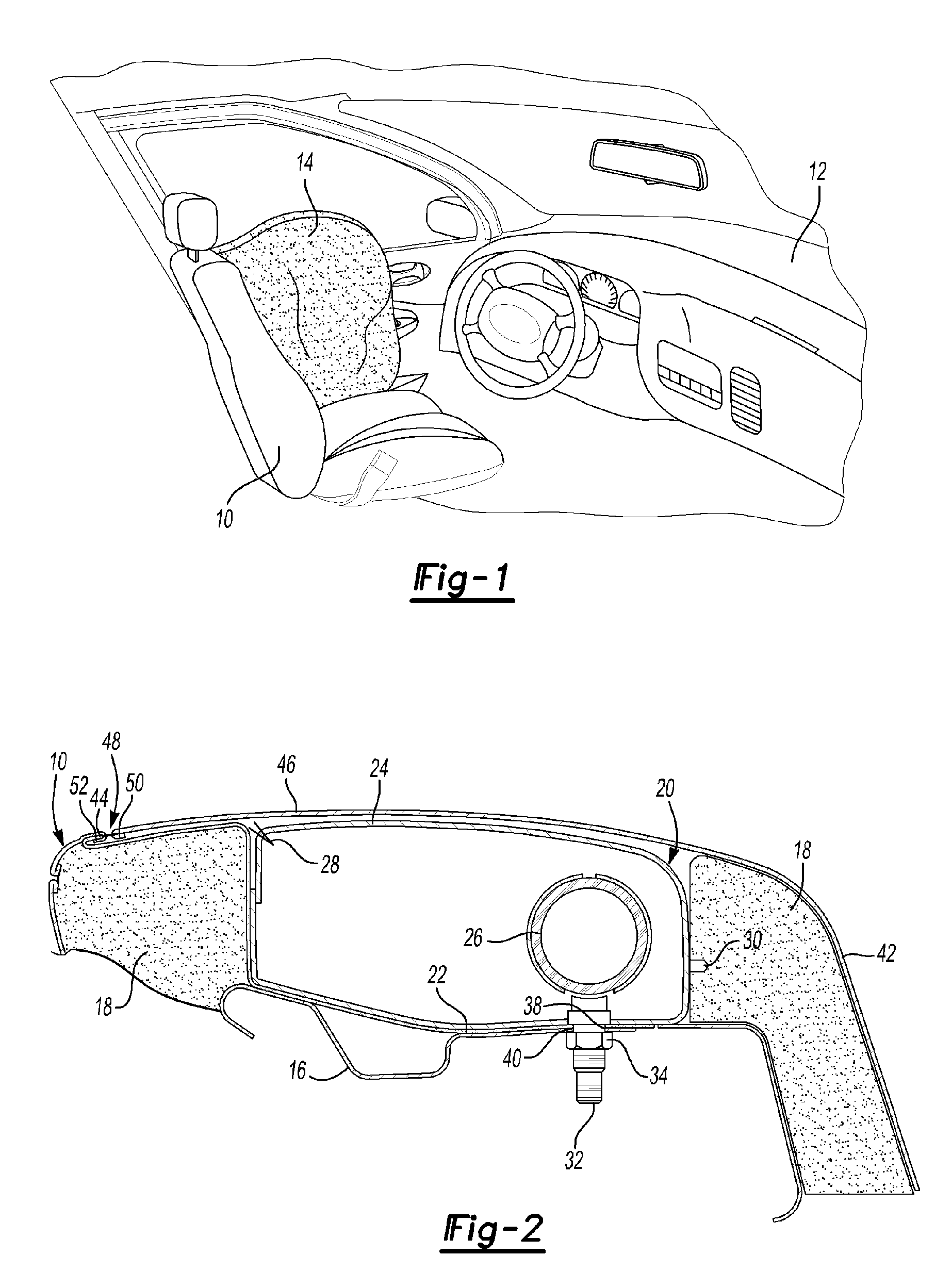
[0023] Referring now to FIG. 1, a seat 10 for vehicle 12 is shown with a side air bag 14 during deployment. The side air bag 14 is deployed in the event of a side impact to the vehicle 12. The side air bag 14 is deployed between the seat 10 and adjacent side of the vehicle 12 which is in most instances a vehicle door.

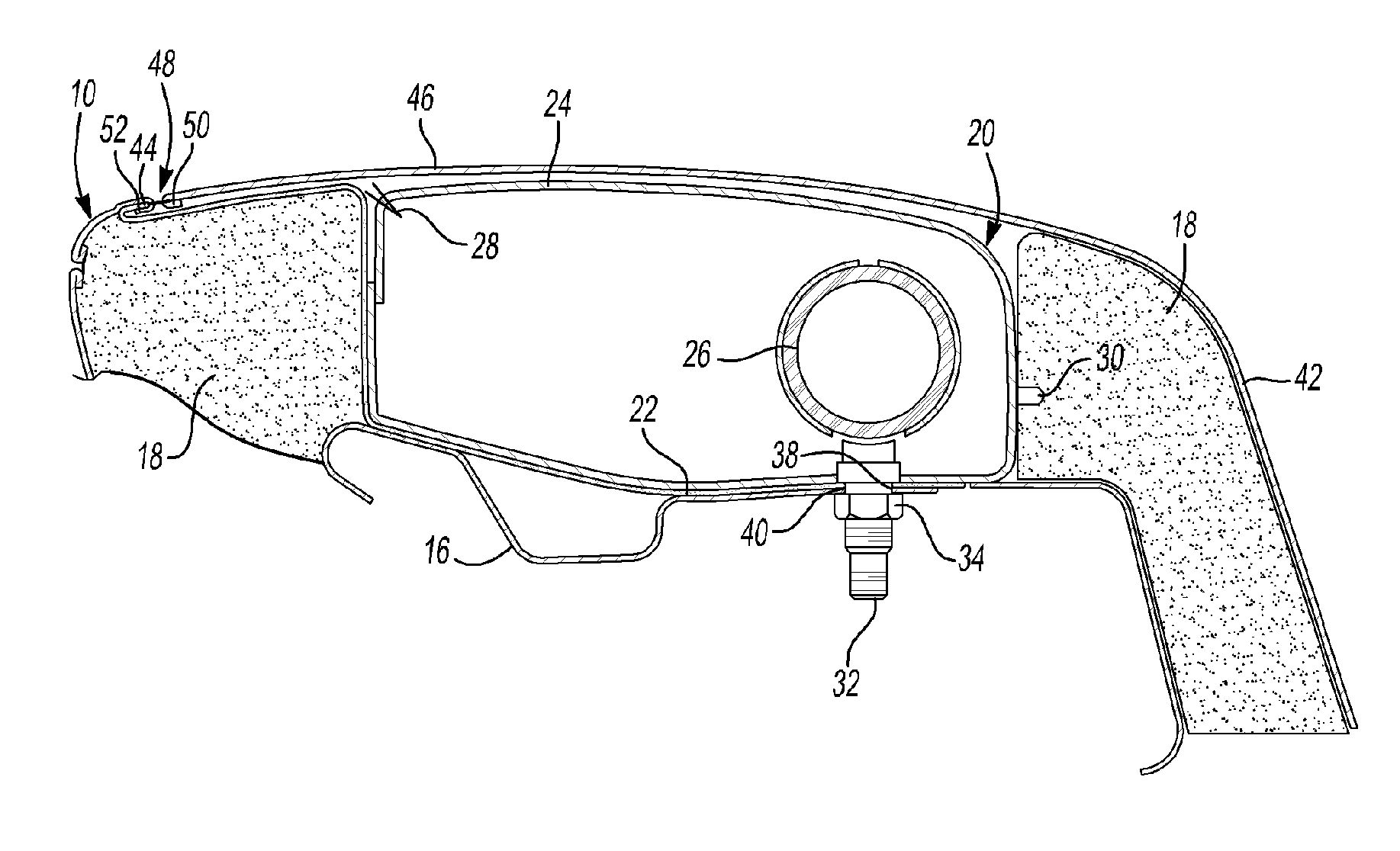
[0024] Referring to FIG. 2, the seat 10 is shown to comprise a frame 16 to which foam pads 18 are secured to form the seat structure. An air bag module 20 is received in the pocket 22 defined by adjacent foam pads 18. The air bag module 20 has a housing 24 in which the air bag 14 is received in a folded manner. An inflator 26 is a pyrotechnic device disposed within the housing 24 for rapidly inflating the air bag 14 in the event of a side impact. As the air bag 14 is inflated by the inflator 22, it separates the housing 24 at a split line 28. A butterfly hinge 30 may be provided generally on the opposite side of the housing 24 from the split line 28. The hinge 30 perm...


PUM


Abstract

A side air bag restraint sub-assembly is disposed in a cavity in a vehicle seat. A reinforcement panel is secured to either the inflator bolts or the seat fame on one edge. The opposite edge of the reinforcement panel is sewn to a hem on one side of a tear seam.

Description

BACKGROUND OF THE INVENTION [0001] 1. Field of the Invention [0002] The present invention relates to a system for a vehicle seat mounted side air bag restraint. [0003] 2. Background Art [0004] Air bag restraint systems for a vehicle seat are used to protect vehicle occupants in the event of a side impact. Air bag restraint systems must deploy rapidly and predictably to be effective. Vehicle seats generally include a rigid frame to which urethane foam pads are secured. The seat is typically enveloped within a cover made of vinyl, cloth or leather. An air bag module, including an air bag and an inflator system, is secured to the seat frame. [0005] The softness and elasticity of covering materials and urethane foam padding present problems for air bag deployment. As the air bag deploys, it must be channeled so that the air bag deploys through an air bag tear seam in the seat cover material. The elasticity of the seat cover material allows the air bag to expand and cause the seat cover ...

Claims


Application Information

Patent Timeline
IPC IPC(8): B60R21/207
CPCB60R21/207B60R21/2165B60R21/2176B60R2021/23146
Inventor TRACHT, MICHAEL L.
Owner LEAR CORP
Why Eureka
Try Eureka