Power slide device for vehicle sliding door

Inactive Publication Date: 2006-06-01
MITSUI KINZOKU ACT
View PDF18 Cites 23 Cited by
  • Summary
  • Abstract
  • Description
  • Claims
  • Application Information

AI Technical Summary

Benefits of technology

[0016] Another object of this invention is to provide a connection structure which enables easy connection of a wire cable to a lower roller bracket and a c

Problems solved by technology

A disadvantage in disposing the tension mechanism on the brackets G, H is that the brackets G, H tend to be longer in a lengthwise direction of the guide rails, and if the brackets G, H have been elongated dead spaces prohibiting the entry of the sliding door B are created at the both ends of the guide rails.
Another disadvantage is that the wire cable is bent with respect to a case of the tension mechanism mounted on the brackets G, H when the roller brackets G, H pass along the curved sections.
If bent, the tension mechanism may fail to perform initial functions because of incremental friction acting on the wire cable and the wire cable may be damaged.
Also, with such obje

Method used


Image

  • Power slide device for vehicle sliding door
  • Power slide device for vehicle sliding door
  • Power slide device for vehicle sliding door

Examples


Embodiment Construction

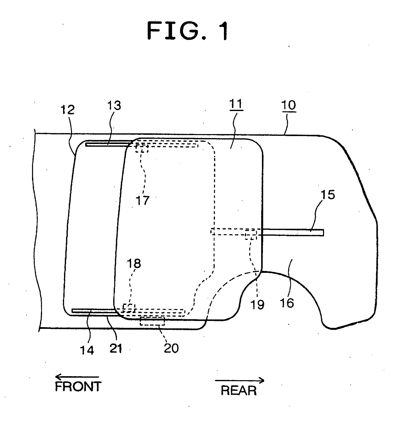
[0026]FIG. 1 is a side view of a typical vehicle body 10 provided with a sliding door 11. On the side face of the vehicle body 10 a door aperture 12 closable by the sliding door 11 is formed. An upper guide rail 13 is fixed to the vehicle body 10 in the proximity of an upper part of the door aperture 12, a lower guide rail 14 is secured to the vehicle body 10 in the proximity of a lower part of the door aperture 12, and a center guide rail 15 is fixedly attached to a quarter panel 16 constituting a rearward side wall of the vehicle body 10. The sliding door 11 is provided with an upper roller bracket 17 slidably engaged with the upper guide rail 13, a lower roller bracket 18 slidably engaged with the lower guide rail 14, and a center roller bracket 19 slidably engaged with the center guide rail 15. Respective brackets 17, 18, 19 are preferable to be rotatably pivoted on the sliding door 11. The sliding door 11 is slidably mounted on the vehicle body 10 in the door-opening direction ...


PUM


Abstract

This slide device comprises a first tension member connected to a distal end of an opening cable, a second tension member connected to a distal end of a closing cable, a lower roller bracket rotatably mounted on a sliding door, a first pin disposed at a front portion of a lower roller bracket, and a second pin disposed at a rear portion of the lower roller bracket. The front of the first tension member is rotatably connected to the first pin and the rear of the second tension member is rotatably connected to the second pin. The first tension member and the second tension member overlap with each other.

Description

FIELD OF THE INVENTION [0001] This invention relates to a power slide device for a vehicle sliding door, more particularly to a tension mechanism of the power slide device and a connection structure for a wire cable of the power drive device and a connection method. DESCRIPTION OF THE RELATED ART [0002] Power drive devices having a sliding door slidably mounted on a plurality of guide rails provided on a vehicle body, a power unit provided with a wire drum rotatable with a driving force generated by a motor, and a wire cable connecting the sliding door to the power unit, and are configured to cause the sliding door to slidingly move to the door-open direction or the door-closing direction are well known. [0003] In general, the power unit may be disposed beneath a floor body in the proximity of a door aperture of the vehicle body (Japanese Utility Model Application Laid-Open No. 3-76982) or in an inner space of a quarter panel of the vehicle body (Japanese Patent Application Laid-Ope...

Claims


Application Information

Patent Timeline
IPC IPC(8): B60J5/06
CPCB60J5/06E05F15/646E05Y2900/531
Inventor YOKOMORI, KAZUHITOSATOH, HIROSHI
Owner MITSUI KINZOKU ACT
Why Eureka
Try Eureka