
Method for operating an injection valve of an internal combustion engine

a technology of injection valve and internal combustion engine, which is applied in the direction of electrical control, process and machine control, instruments, etc., can solve the problems of increased risk, inability to ensure adequate scavenging effect, and irreparable engine damag

Inactive Publication Date: 2006-06-01
ROBERT BOSCH GMBH
View PDF3 Cites 5 Cited by
  • Summary
  • Abstract
  • Description
  • Claims
  • Application Information

AI Technical Summary

Problems solved by technology

Damage caused by a gasoline-filled cylinder occurs when the cross section of the injection valve is blocked by dirt particles, thereby preventing the injection valve from closing completely.
If other cylinders in the internal combustion engine are functioning properly at this time, they exert—via the crankshaft—very strong forces on the connecting rod and the piston of the blocked cylinder, which usually results in irreparable engine damage, particularly in the form of the connecting rod breaking and a damaged cylinder.
In these operating states of the internal combustion engine, an adequate scavenging effect is no longer ensured, due to the partial-stroke actuation.
This results in a greatly increased risk that the injection nozzle will become soiled and make it more difficult to detect such soiling.
During idle operation in particular, two injection cycles of a cylinder can be separated by a long period of time.
As a result, only relatively few injection events are available for diagnosing the undesired jammed-open operating state of the nozzle needle; this makes diagnosis of this operating state less reliable overall.

Method used


Image

  • Method for operating an injection valve of an internal combustion engine
  • Method for operating an injection valve of an internal combustion engine
  • Method for operating an injection valve of an internal combustion engine

Examples


Embodiment Construction

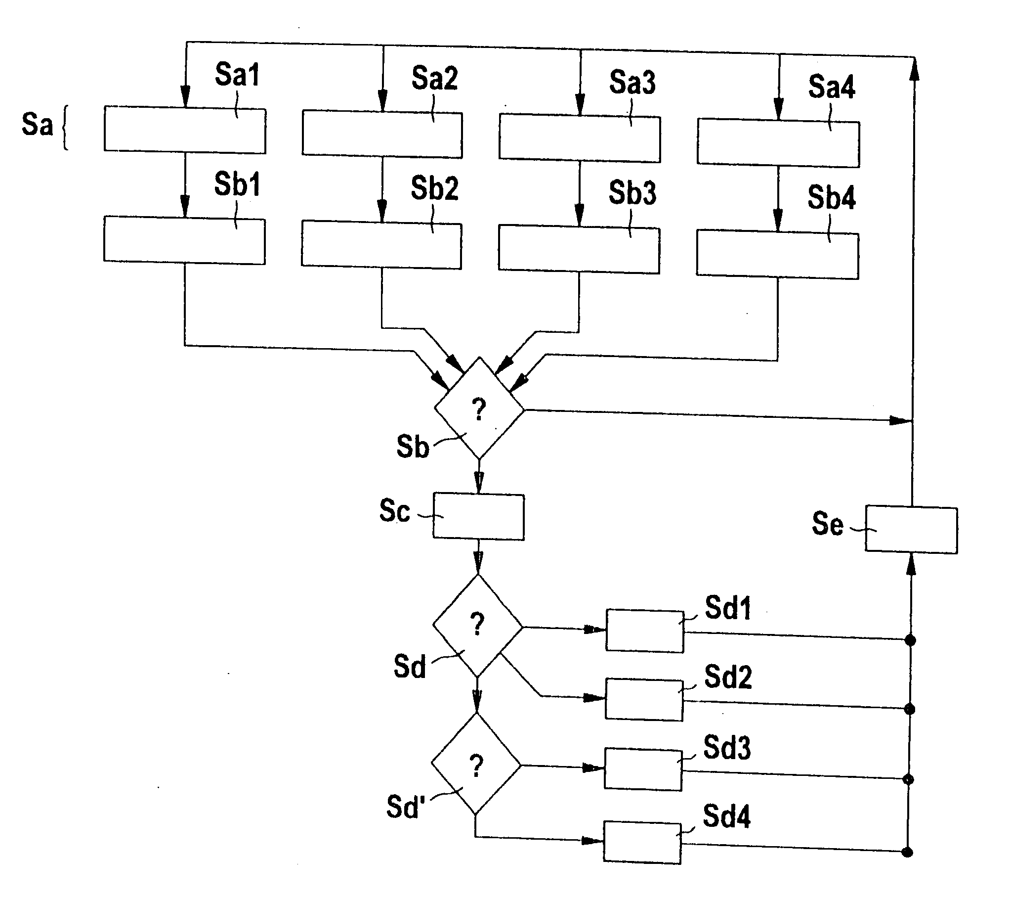
[0031] The method according to the present invention serves to prevent soiling of nozzle 310 of injection valve 300, in particular during operating states in which a small amount of fuel is required, such as idling.

[0032] To this end, the method according to a step Sa) provides that the internal combustion engine is monitored for proper functioning. This monitoring can take place via one of four methods, according to the present invention.

[0033] In one form of this monitoring, the air-fuel mixture of the internal combustion engine is monitored to determine when it becomes rich, as indicated by method step Sa1. The fuel mixture is determined to have become richer typically via a reduction in the lambda value for the cylinder involved.

[0034] According to a second form of monitoring the internal combustion engine, said internal combustion engine or any of its cylinders is monitored for the occurrence of misfires, as proposed in method step Sa2. In this case, a misfire is understood ...


PUM


Abstract

The present invention relates to a method for operating an injection valve of an internal combustion engine, whereby the metering of fuel is adjustable in particular by varying the stroke of the nozzle needle of the injection valve. Methods and injections valves of this type are generally known from the related art. The aim of the present invention is to provide a method which makes it possible to prevent an incomplete closure of the valve due to soiling (the risk of damage caused by a gasoline-filled cylinder) in operating states of the internal combustion engine in which no complete strokes of the nozzle needle occur over a prolonged period of time and the nozzle is therefore not sufficiently scavenged. According to the present invention, the nozzle is scavenged with fuel when a jammed-open operating state of the nozzle needle is detected.

Description

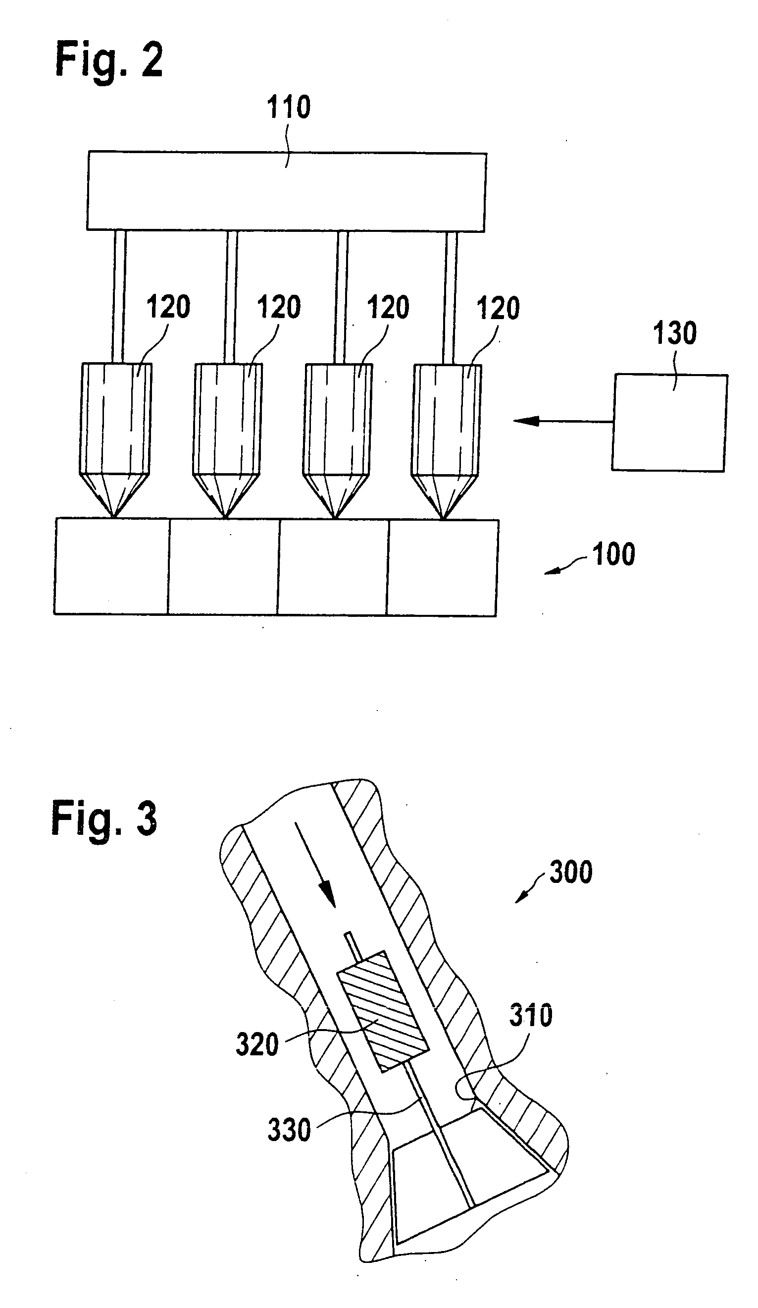
[0001] The present invention relates to a method for operating an injection valve of an internal combustion engine, whereby the metering of fuel is adjustable in particular by varying the stroke of the nozzle needle of the injection valve. The present invention also relates to a computer program and a control device for carrying out the method, and an internal combustion engine with a control device of this type. BACKGROUND INFORMATION [0002] High-pressure fuel injection valves for direct fuel injection in the context of internal combustion engines are generally known. Specific types of high-pressure fuel injection valves 300, as shown in FIG. 3, are also known, in particular, with which it is possible to meter the fuel to be injected into the combustion chambers of the internal combustion engine via the opening time of the valve, and, in particular, by varying the stroke of valve needle 330. With these valves, nozzle needle 330 is actuated, e.g., directly with the aid of a piezoele...

Claims


Application Information

Patent Timeline
IPC IPC(8): F02D41/22F02B1/02F02D41/20F02M61/16F02M63/00
CPCF02B1/02F02D41/20F02D41/221F02D2041/225F02D2200/0602F02M61/161F02M2200/06F02M2200/18Y02T10/40
Inventor JOOS, KLAUSPANTRING, JUERGEN
Owner ROBERT BOSCH GMBH
Learn More