Vehicular shift lock device having pivotal stopper and linkage devices
a technology of shift lock and pivot stopper, which is applied in the direction of mechanical control device, process and machine control, instruments, etc., can solve the problems of large required operating stroke of manually operable members and difficulty in sufficiently amplifying operating stroke, and achieve the effect of reducing the required operating strok
- Summary
- Abstract
- Description
- Claims
- Application Information
AI Technical Summary
Benefits of technology
Problems solved by technology
Method used
Image
Examples
first embodiment
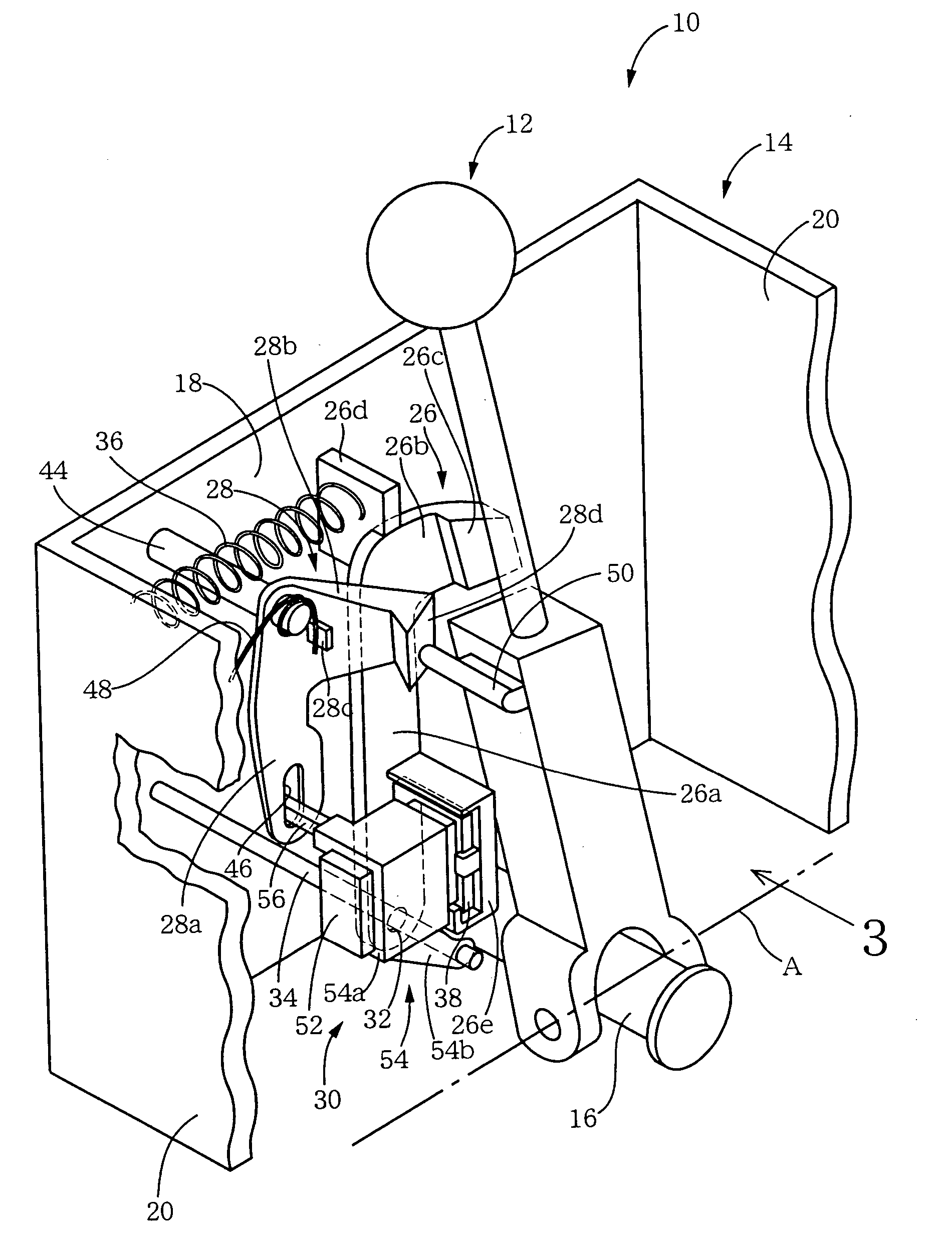
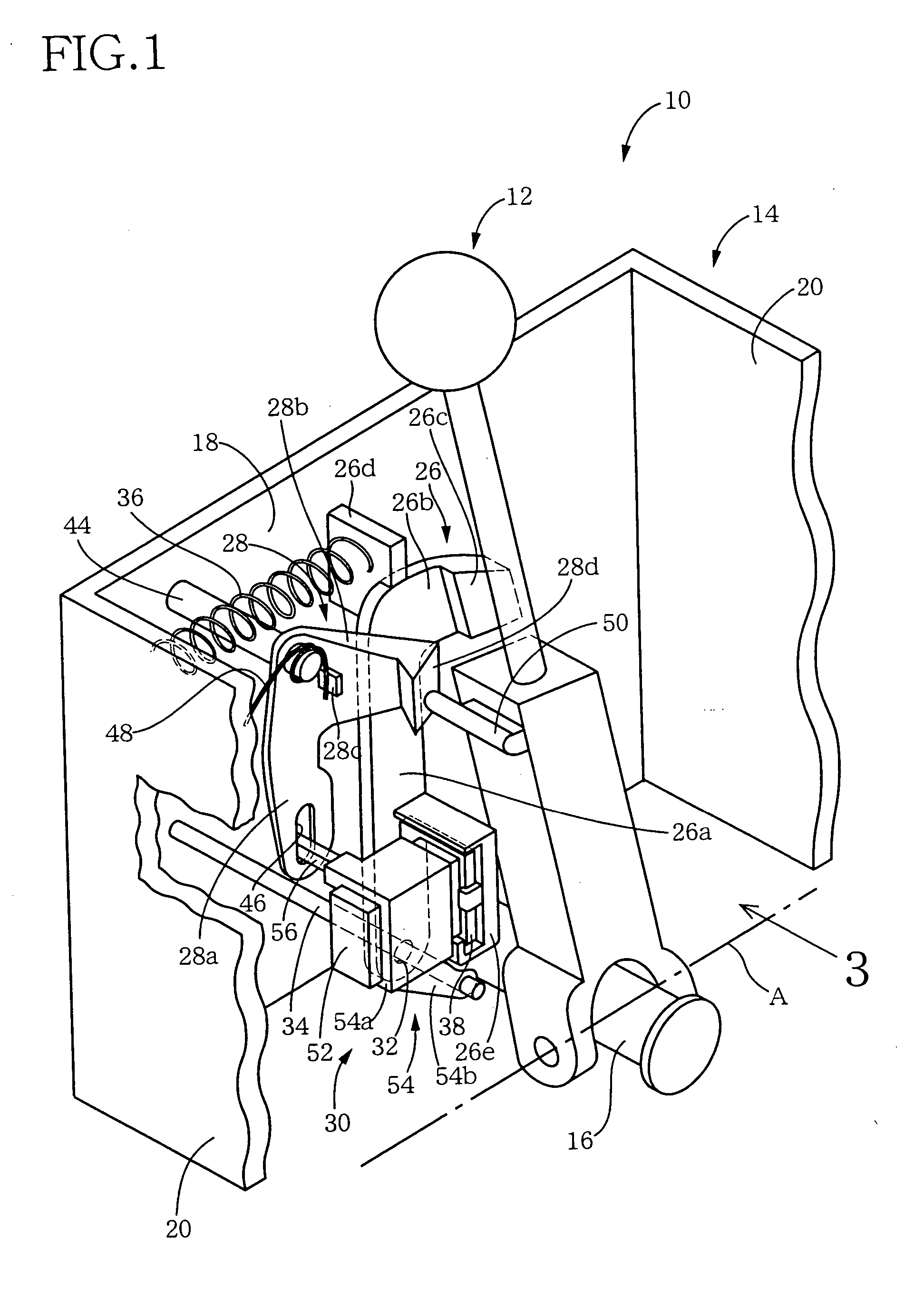
[0027] Referring first to the perspective view of FIG. 1, there is schematically shown the construction of a vehicular shift lock device 10 constructed according to this invention. The shift lock device 10 is operable between a locking state for inhibiting a movement of a shift lever 12 and an unlocking state for permitting the movement of the shift lever 12. As shown in FIG. 1, the shift lock device 10 has a casing 14 by which a transversal shaft 16 is supported. The transversal shaft 16 extends in the transversal or lateral direction of an automotive vehicle provided with an automatic transmission (not shown) a shifting action of which is controlled by the shift lever 12. The shift lever 12 is pivotable about the transversal shaft 16, and a longitudinal shaft (not shown) which has an axis A perpendicular to the axis of the transversal shaft 16 and extends in the longitudinal or running direction of the vehicle.
[0028] The casing 14 has a pair of parallel longitudinal walls 18 (one ...
second embodiment
[0052] In the shift lock device 100 of the second embodiment, too, the stopper link 126, cam link 128 and solenoid link 130 which are moved by the lateral pivotal movement of the shift lever to place the shift lock device 100 in the unlocking state are all arranged to be pivotally moved rather than linearly moved, making it possible to easily amplify the operating stroke of the shift lever, thereby reducing the required operating stroke of the shift lever.
[0053] While the preferred embodiments have been described in detail by reference to the drawings, it is to be understood that the present invention may be otherwise embodied.
[0054] In the illustrated first embodiment, the shift lock devices 10, 100 in the first and second embodiments are provided for the shifting device of the gate type wherein the shift lever 12 functions as the manually operable member operable to place the shift lock device 10, 100 in its unlocking state. However, the shift lock device according to the present...
third embodiment
[0056] In the illustrated embodiments, the solenoid link 30, 130 functioning as the second linkage device is connectable to the stopper link 26, 126 by an electromagnetic force generated by the solenoid 52, 152 to attract the yoke 38, 138. However, the second linkage device may be mechanically connectable to the stopper link 26, 126. An example of a mechanism arranged to connect the second linkage device and the stopper member is shown in FIG. 6. A shift lock device incorporating this mechanism includes a second linkage device 160 which has a main body portion 160a accommodating an actuator (not shown). The shift lock device includes an engaging pin 162 which is axially movable by the actuator in a direction parallel to the first support shaft 34, between an advanced position and a retracted position. The stopper link 26 of this shift lock device has a through-hole 164 formed in its long plate portion 26a. In the advanced position of the pin 162, the pin 162 is held in engagement w...
PUM
 Abstract
Description
Claims
Application Information
 - R&D
- Intellectual Property
- Life Sciences
- Materials
- Tech Scout
- Unparalleled Data Quality
- Higher Quality Content
- 60% Fewer Hallucinations
Browse by: Latest US Patents, China's latest patents, Technical Efficacy Thesaurus, Application Domain, Technology Topic, Popular Technical Reports.
© 2025 PatSnap. All rights reserved.Legal|Privacy policy|Modern Slavery Act Transparency Statement|Sitemap|About US| Contact US: help@patsnap.com


