
Vehicular shift lock device having pivotal stopper and linkage devices

a technology of shift lock and pivot stopper, which is applied in the direction of mechanical control device, process and machine control, instruments, etc., can solve the problems of large required operating stroke of manually operable members and difficulty in sufficiently amplifying operating stroke, and achieve the effect of reducing the required operating strok

Inactive Publication Date: 2010-03-16
TOYOTA JIDOSHA KK +4
View PDF10 Cites 3 Cited by
  • Summary
  • Abstract
  • Description
  • Claims
  • Application Information

AI Technical Summary

Benefits of technology

The solution allows for a significant reduction in the operating stroke of the manually operable member, enhancing ease of operation and stability, while maintaining the shift lock's functionality.

Problems solved by technology

In the shift lock device wherein the lock plate, cam member and stopper member are all linearly moved, it is difficult to sufficiently amplify the operating stroke of the manually operable member into the linear movements, although some degree of amplification of the operating stoke is possible by determining an angle of inclination of the cam surface of the cam member so as to amplify the operating stroke.
Accordingly, the required operating stroke of the manually operable member tends to be large.
This is contrary to the desirability of reducing the required operating stroke of the manually operable member.

Method used


Image

  • Vehicular shift lock device having pivotal stopper and linkage devices
  • Vehicular shift lock device having pivotal stopper and linkage devices
  • Vehicular shift lock device having pivotal stopper and linkage devices

Examples


first embodiment

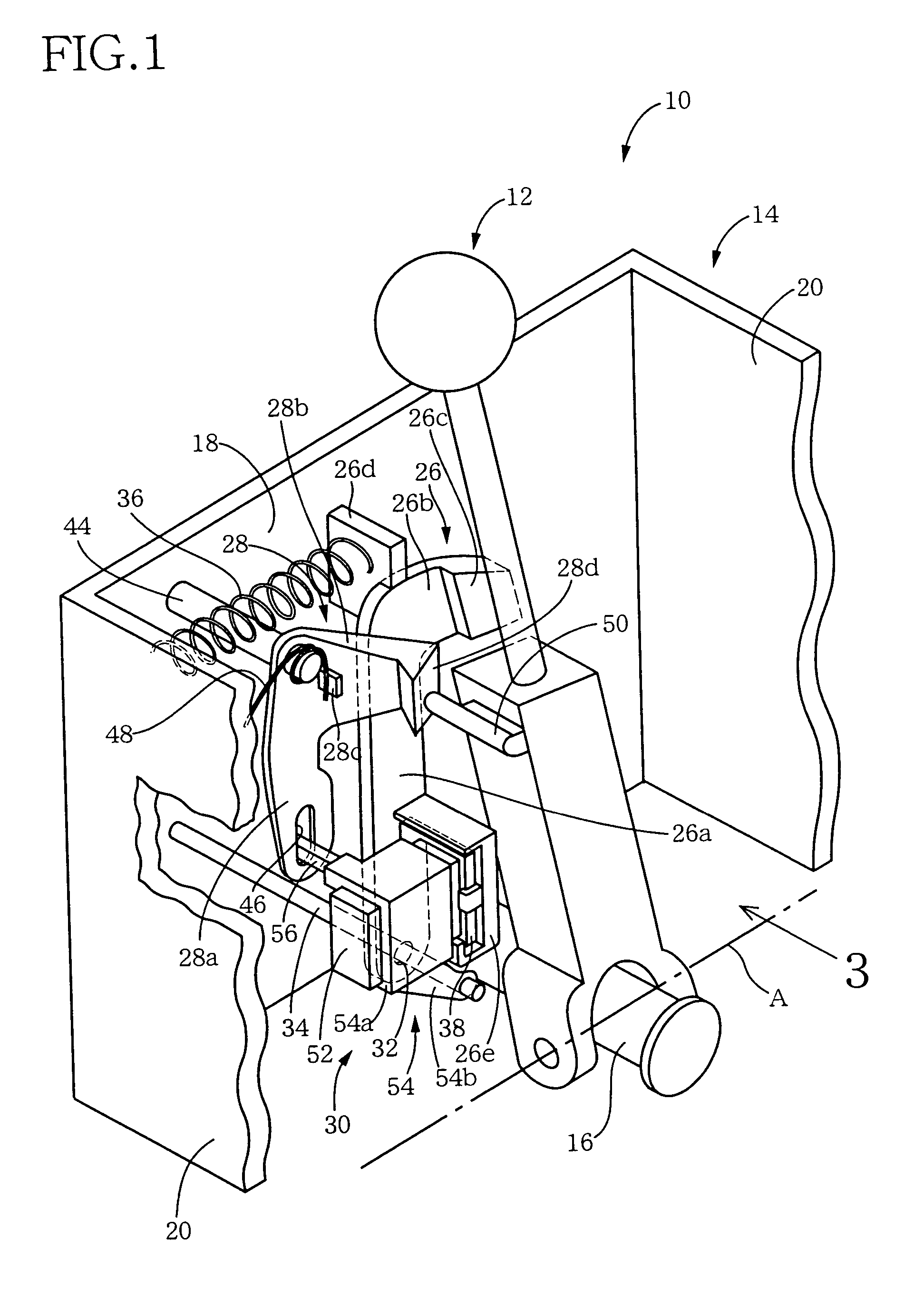
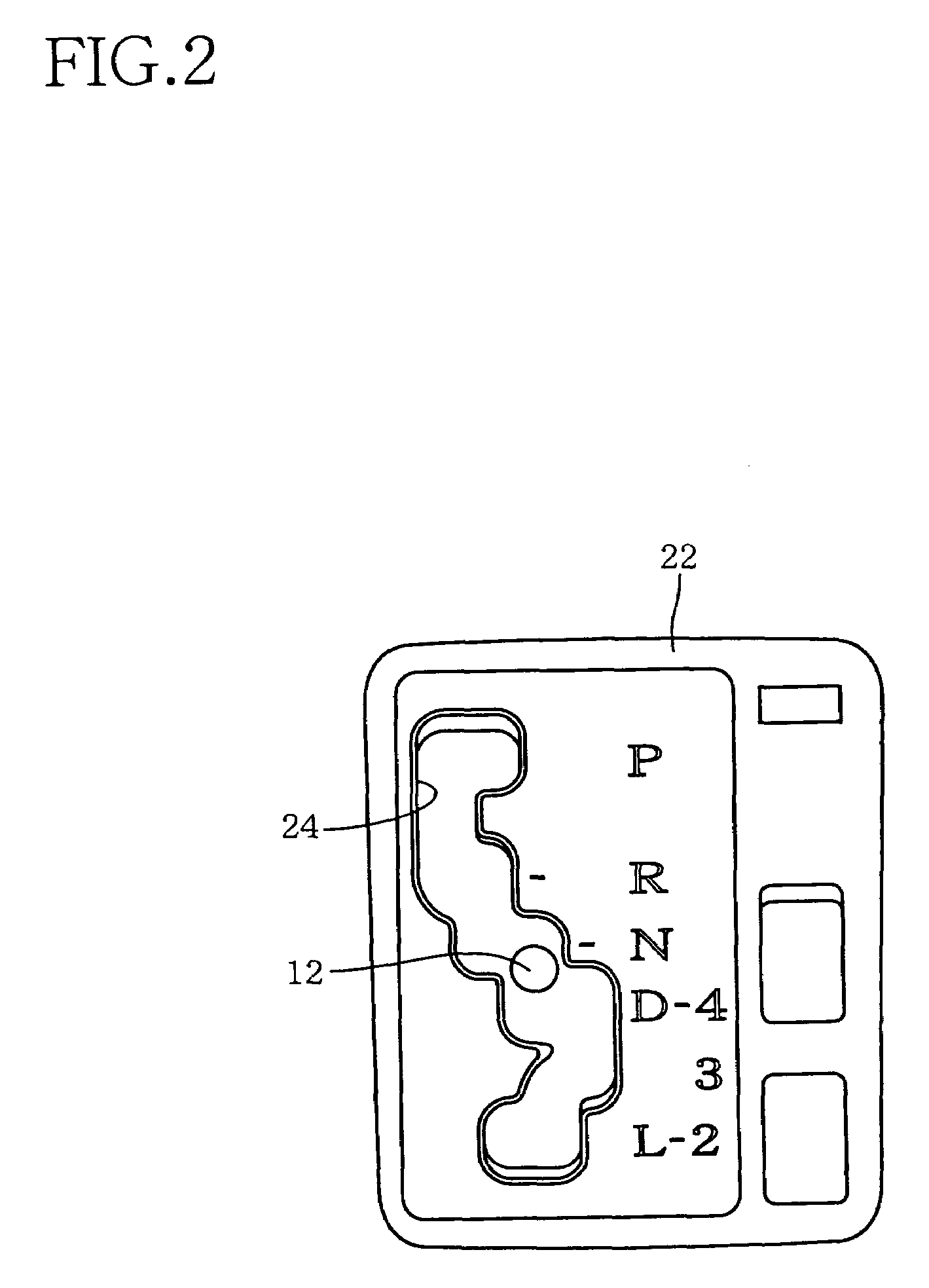
[0027]Referring first to the perspective view of FIG. 1, there is schematically shown the construction of a vehicular shift lock device 10 constructed according to this invention. The shift lock device 10 is operable between a locking state for inhibiting a movement of a shift lever 12 and an unlocking state for permitting the movement of the shift lever 12. As shown in FIG. 1, the shift lock device 10 has a casing 14 by which a transversal shaft 16 is supported. The transversal shaft 16 extends in the transversal or lateral direction of an automotive vehicle provided with an automatic transmission (not shown) a shifting action of which is controlled by the shift lever 12. The shift lever 12 is pivotable about the transversal shaft 16, and a longitudinal shaft (not shown) which has an axis A perpendicular to the axis of the transversal shaft 16 and extends in the longitudinal or running direction of the vehicle.

[0028]The casing 14 has a pair of parallel longitudinal walls 18 (one of...

second embodiment

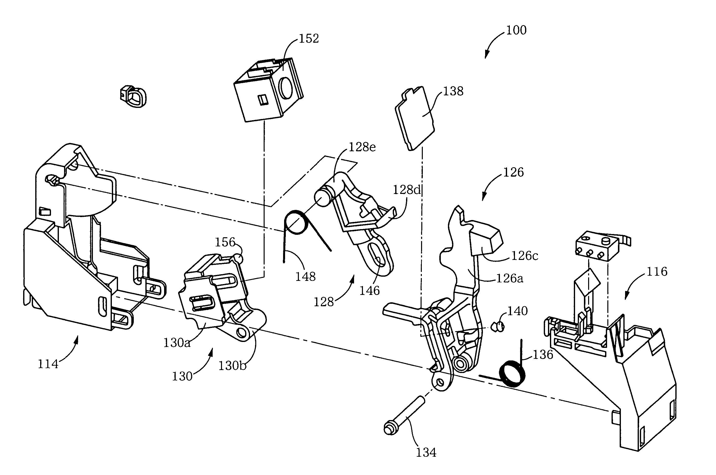
[0052]In the shift lock device 100 of the second embodiment, too, the stopper link 126, cam link 128 and solenoid link 130 which are moved by the lateral pivotal movement of the shift lever to place the shift lock device 100 in the unlocking state are all arranged to be pivotally moved rather than linearly moved, making it possible to easily amplify the operating stroke of the shift lever, thereby reducing the required operating stroke of the shift lever.

[0053]While the preferred embodiments have been described in detail by reference to the drawings, it is to be understood that the present invention may be otherwise embodied.

[0054]In the illustrated first embodiment, the shift lock devices 10, 100 in the first and second embodiments are provided for the shifting device of the gate type wherein the shift lever 12 functions as the manually operable member operable to place the shift lock device 10, 100 in its unlocking state. However, the shift lock device according to the present inv...

third embodiment

[0056]In the illustrated embodiments, the solenoid link 30, 130 functioning as the second linkage device is connectable to the stopper link 26, 126 by an electromagnetic force generated by the solenoid 52, 152 to attract the yoke 38, 138. However, the second linkage device may be mechanically connectable to the stopper link 26, 126. An example of a mechanism arranged to connect the second linkage device and the stopper member is shown in FIG. 6. A shift lock device incorporating this mechanism includes a second linkage device 160 which has a main body portion 160a accommodating an actuator (not shown). The shift lock device includes an engaging pin 162 which is axially movable by the actuator in a direction parallel to the first support shaft 34, between an advanced position and a retracted position. The stopper link 26 of this shift lock device has a through-hole 164 formed in its long plate portion 26a. In the advanced position of the pin 162, the pin 162 is held in engagement wi...


PUM


Abstract

A vehicular shift lock device for selectively inhibiting and permitting a movement of a shift lever, including (a) a stopper member pivotable about an axis between a stopping position and a non-stopping position for respectively preventing and permitting a movement of a manually operable member provided to place the shift lock device in its unlocking state, (b) a first biasing member biasing the stopper member toward the stopping position, (c) a first linkage device pivotable about an axis in a first direction by the movement of the manually operable member, (d) a second biasing member biasing the first linkage device in a second direction opposite to the first direction, and (e) a second linkage device pivotable about an axis to its operated position and having a connected state and a disconnected state in which the second linkage device is connected to and disconnected from the stopper member, respectively, and wherein second linkage device is operatively connected to the first linkage device such that the stopper member is pivoted to the non-stopping position when the second linkage device placed in the connected state is pivoted to the operated position by a pivotal movement of the first linkage device in the first direction.

Description

BACKGROUND OF THE INVENTION[0001]1. Field of the Invention[0002]The present invention relates to a shift lock device operable between its locking and unlocking states for inhibiting and permitting a shifting movement of a shift lever provided in a vehicle such as an automobile.[0003]2. Discussion of Related Art[0004]In the field of automotive vehicles provided with an automatic transmission, there is known a shift lock device having a locking state for locking a shift lever in its parking position. In this locking state, the shift lever is prevented from being operated from the parking position to any other operating position unless a brake pedal is in its operated position. An example of this vehicular shift lock device is disclosed in JP-8-216722A.[0005]The shift lock device disclosed in the above-identified publication is arranged to be placed in its unlocking position when a detent knob provided on the shift lever is operated. This shift lock device includes: a lock plate movabl...

Claims


Application Information

Patent Timeline
Patent Type & Authority Patents(United States)
IPC IPC(8): G05G5/00G05G5/08
CPCF16H59/10F16H61/22G05G5/08Y10T74/20116Y10T74/20085Y10T74/20098
Inventor SHIMIZU, ETSUOKAMEI, YOSHIFUMIMASUDA, TAKAYOSHISHINDO, YOSHIYUKIUEMURA, SHINICHITAKEUCHI, YASUNORI
Owner TOYOTA JIDOSHA KK
Learn More