Device for mounting a wheel to the frame of a bicycle

a technology of fast tightening mechanism and bicycle, which is applied in the direction of hubs, axle suspensions, cycle equipments, etc., can solve the problems of substantial axial space requirement, large axial distance requirement, and inaccurate axial positioning of the median plane of the wheel, so as to reduce the risk of the wheel being separated when subjected to lateral for

Inactive Publication Date: 2006-06-08
SALOMON SA
View PDF8 Cites 3 Cited by
  • Summary
  • Abstract
  • Description
  • Claims
  • Application Information

AI Technical Summary

Benefits of technology

[0018] Due to the spacing of the inner and outer zones of axial support zones by a distance greater than 20 mm, or greater than 25 mm, for the same tightening torque, the risk of the wheel being separated when subjected to a lateral force is reduced.

Problems solved by technology

In addition, when the wheel is demounted, the hub has a substantial length that projects and risks being damaged during handling or when the bicycle is stored without a wheel.
Although such a surface allows combining the centering of the wheel and the transmission of the lateral forces to which the wheel is subjected, it presents numerous drawbacks.
First, it has a substantial axial space requirement in the area of the hub.
It can also be a cause for inaccurate axial positioning of the median plane of the wheel.
Another drawback of the device disclosed in EP 1 153 827 is that one has to make an accurate angular positioning of the wheel before being able to actuate the tightening mechanism, due to the presence of three pins provided for transmitting the driving torque of the chain.
Finally, a major drawback of this type of construction lies in the clearance between the pins and the housings in which they are lodged.

Method used


Image

  • Device for mounting a wheel to the frame of a bicycle
  • Device for mounting a wheel to the frame of a bicycle
  • Device for mounting a wheel to the frame of a bicycle

Examples


Embodiment Construction

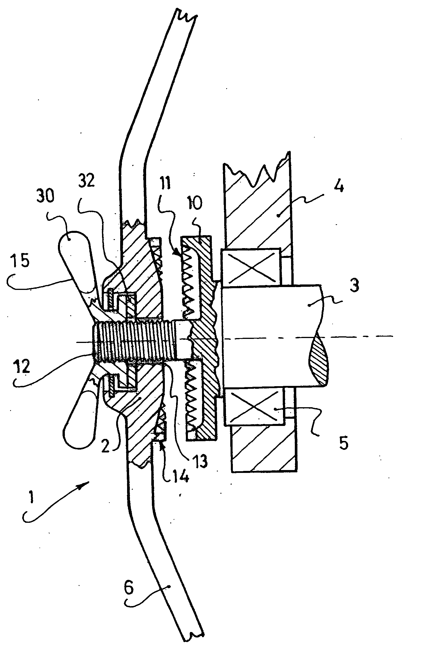
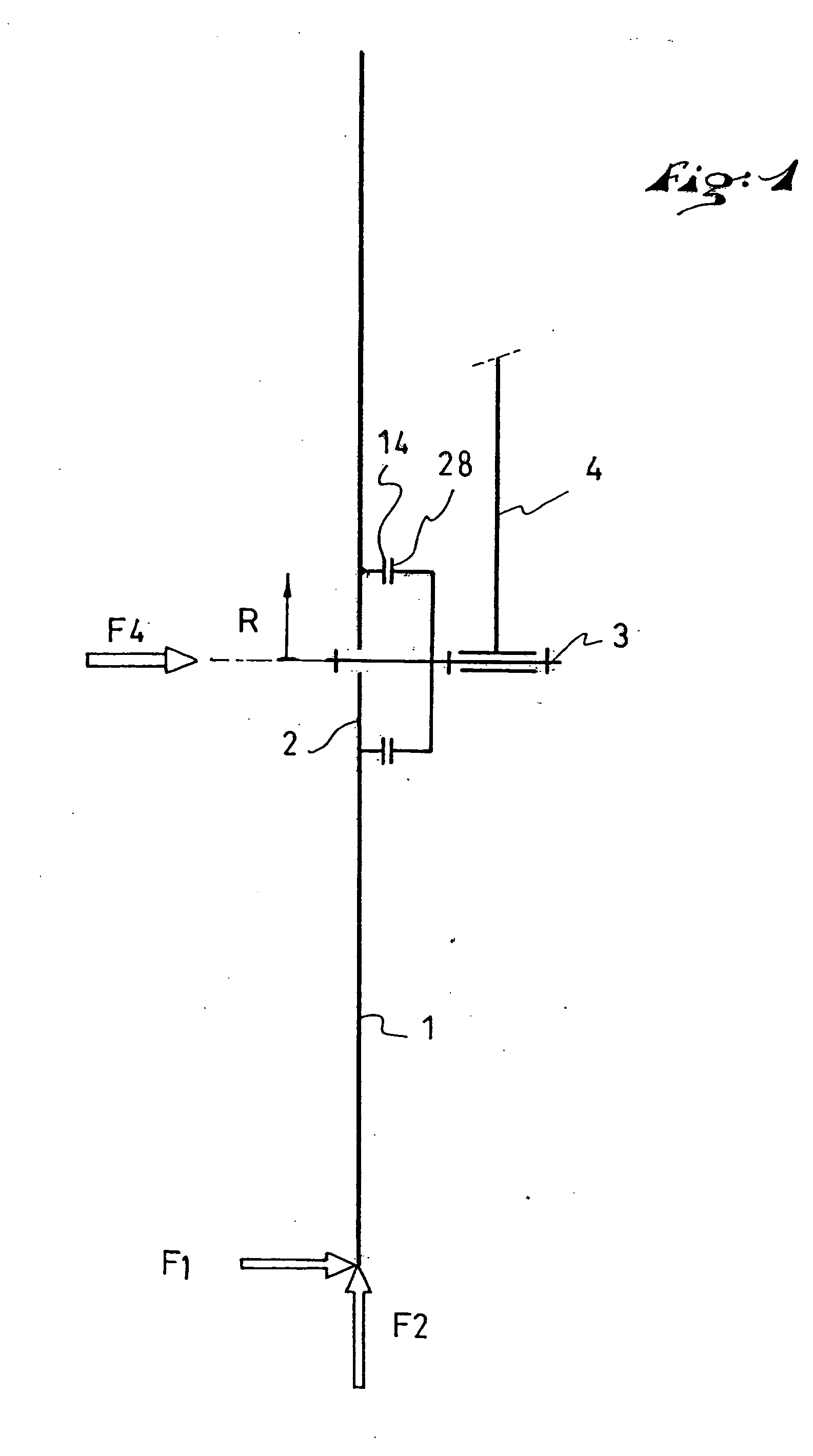
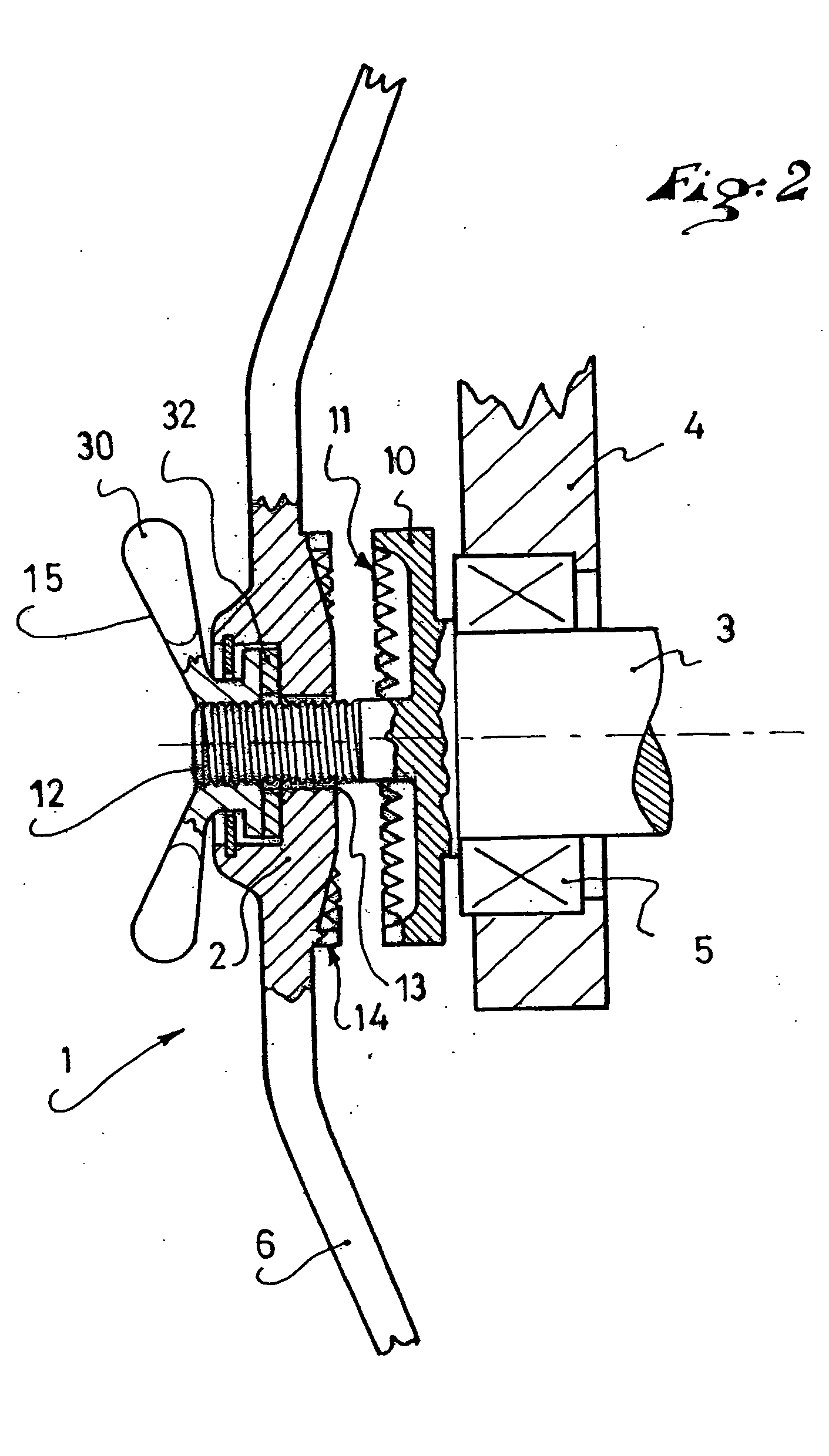
[0028]FIG. 1 shows a schematic functional diagram of a device for mounting a wheel 1 to a frame 4 according to the invention. An inner hub 3 is rotatably mounted relative to the frame 4. The inner hub 3 includes axial support areas distributed in the vicinity of a circle having a radius R. An outer hub 2 of the wheel 1 includes outer axial support areas 14 corresponding to the axial support areas 28 of the inner hub 3. The axial support areas 28 of the inner hub 3 are also distributed in the vicinity of a circle having a radius R. A centering arrangement ensures accurate positioning of the wheel on the inner hub 3. The diagram of FIG. 1 does not take into account the presence of transmission elements, transmitting the chain torque of the inner hub to the wheel. The diagram of FIG. 1 also does not show the chain torque, nor the torque to which the wheel is subjected during braking.

[0029] Generally speaking, the periphery of the wheel 1 could be subjected to a lateral force estimated...


PUM


Abstract

A device for mounting a wheel of a bicycle onto a frame, including an inner hub rotatably mounted on the frame and equipped with an inner axial support area, an outer hub connected to the rim of the wheel by means of traction spokes, compression spokes, or flanges, and including an outer axial support area that cooperates with the inner axial support area, a mechanism for tightening the outer hub on the inner hub, the inner and outer axial support areas being located at a distance from the axis of the wheel at least greater than 20 mm, or greater than 25 mm, and distributed along the vicinity of a circle having a radius greater than 25 mm, centered on the axis of the wheel. The inner and outer axial support areas include a plurality of teeth forming part of a transmission mechanism.

Description

CROSS-REFERENCE TO RELATED APPLICATIONS [0001] This application is a continuation of PCT International Patent Application No. PCT / FR2004 / 001311, filed on May 27, 2004, the disclosure of which is hereby incorporated by reference thereto in its entirety, and the priority of which is claimed under 35 U.S.C. §120, pursuant to the provisions of 35 U.S.C. §363. [0002] This application claims priority under 35 U.S.C. §119 of French Patent Application No. 03.06546, filed on May 28, 2003, the disclosure of which is hereby incorporated by reference thereto in its entirety.BACKGROUND OF THE INVENTION [0003] 1. Field of the Invention [0004] The invention relates to a device for mounting a bicycle wheel to a frame with a quick-tightening mechanism, and a bicycle that includes such device. More particularly, the invention relates to such a device for mounting and demounting a bicycle wheel with a quick-tightening mechanism and, more particularly, for bicycles having frames with a projecting singl...

Claims


Application Information

Patent Timeline
Patent Type & Authority Applications(United States)
IPC IPC(8): B60B27/00B62K25/00
CPCB62K25/005
Inventor MERCAT, JEAN-PIERREHILLAIRET, JEAN-MARC
Owner SALOMON SA
Why Eureka
Try Eureka