

Piezoelectric driving type MEMS apparatus
a driving type, mems technology, applied in the direction of relays, generators/motors, capacitors with electrode distance variation, etc., can solve the problems of change in capacitance value, inability to obtain desired capacitance value, and inability to obtain desired properties
- Summary
- Abstract
- Description
- Claims
- Application Information
AI Technical Summary
Problems solved by technology
Method used
Image

Examples
first embodiment
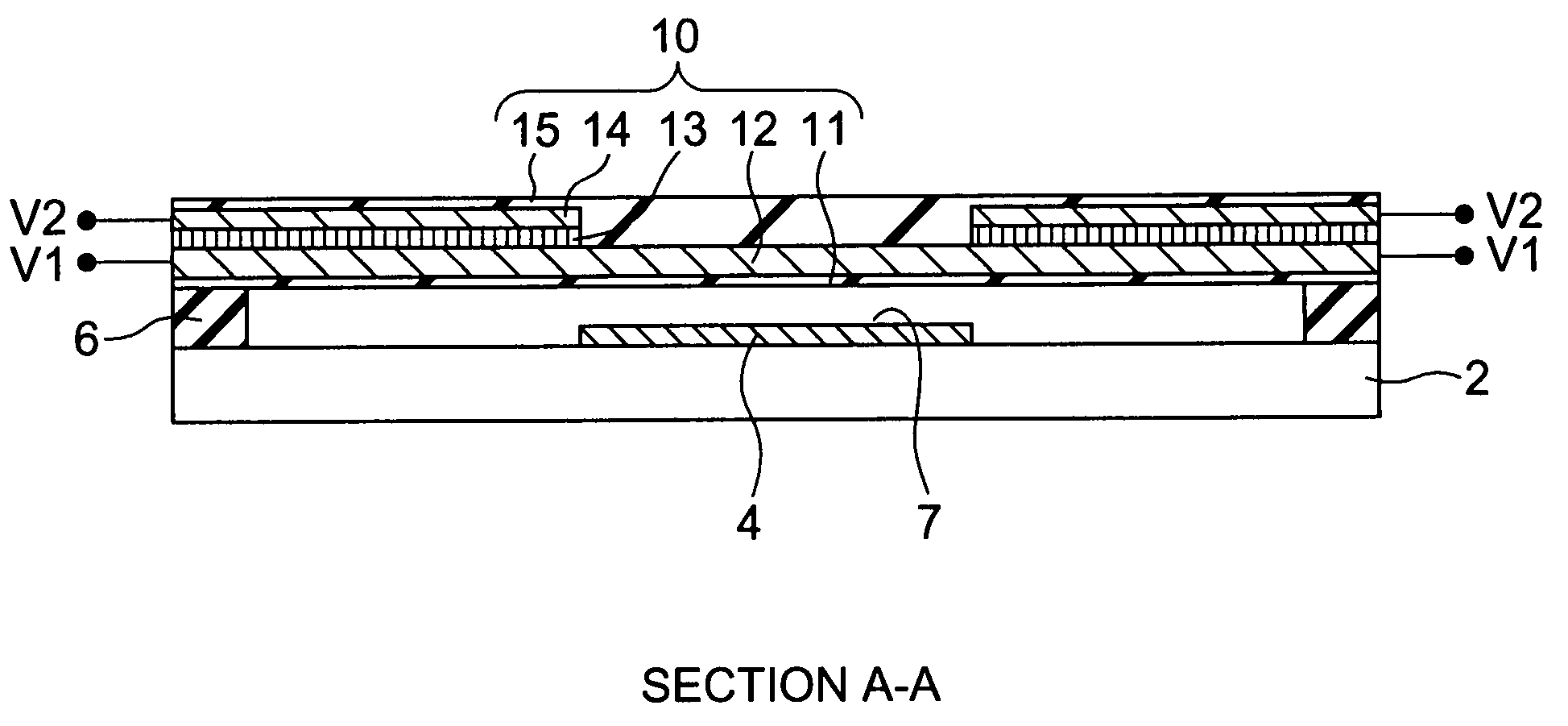
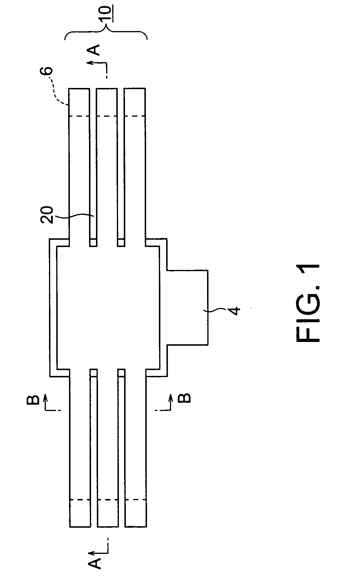
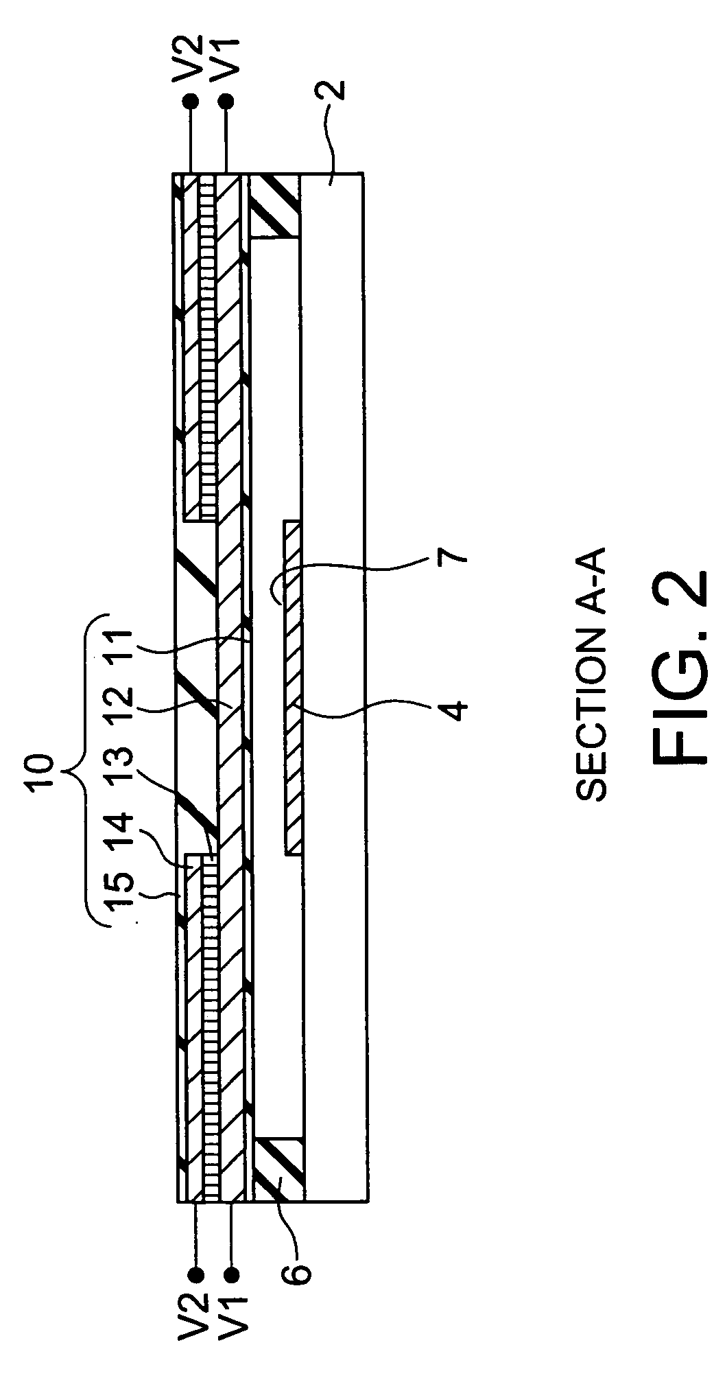
[0046] A piezoelectric driving type MEMS apparatus according to a first embodiment of the invention will be explained with reference to FIGS. 1 to 3. FIG. 1 is a plan view of the piezoelectric driving type MEMS apparatus according to the embodiment, FIG. 2 is a sectional view of the piezoelectric driving type MEMS apparatus according to the embodiment taken along line A-A shown in FIG. 1, and FIG. 3 is a sectional view of the piezoelectric driving type MEMS apparatus according to the embodiment taken along line B-B shown in FIG. 1.
[0047] The piezoelectric driving type MEMS apparatus according to the embodiment is a variable capacitor which has such a constitution that a lower electrode 4 is provided on a central portion of a substrate 2 made from silicon or glass, and a plurality of (for example, three) supporting portions 6 are provided at each of both end portions of the substrate 2 so as to be opposed to corresponding supporting portions 6 at the other end portion thereof. Furth...
second embodiment
[0056] Next, a piezoelectric driving type MEMS apparatus according to a second embodiment of the invention will be explained with reference to FIGS. 5 and 6. FIG. 5 is a plan view showing a constitution of a piezoelectric driving type MEMS apparatus according to the embodiment and FIG. 6 is a sectional view of the piezoelectric driving type MEMS apparatus taken along line A-A shown in FIG. 5.
[0057] The MEMS apparatus according to the embodiment is an MEMS switch, which has such a constitution that a supporting portion 6 is provided at one end of a silicon substrate 2, a pair of lower electrodes 37 and leading electrodes 38 are provided at the other end thereof, and a cantilever beam 30 is fixed on the supporting portion 6. The cantilever beam 30 is provided with an insulating film 31, a first electrode 32 provided on the insulating film 31, a piezoelectric film 33 provided on the first electrode 32, a second electrode 34 provided on the piezoelectric film 33, a protective film 35 p...
third embodiment
[0061] Next, a piezoelectric driving type MEMS apparatus according to a third embodiment of the invention will be explained with reference to FIGS. 7 to 9. FIG. 7 is a plan view of the piezoelectric driving type MEMS apparatus according to the embodiment, FIG. 8 is a sectional view of the piezoelectric driving type MEMS apparatus taken along line A-A shown in FIG. 7, and FIG. 9 is a sectional view of the piezoelectric driving type MEMS apparatus taken along line B-B shown in FIG. 7. Incidentally, FIG. 7 is a plan view where a protective film described later has been removed.
[0062] The piezoelectric driving type MEMS apparatus according to the embodiment is a T-shaped type unimorph variable capacitor, which is provided with a lower electrode 4 and a beam 10. The lower electrode 4 is provided at a central portion of a substrate 2 made from silicon and formed thereon with an insulating layer 3 made from, for example, SiO2, and an insulating layer 5 made from, for example, SiN is forme...
PUM
 Abstract
Description
Claims
Application Information