Method and apparatus for encoding/decoding video signal using motion vectors of pictures in base layer

a technology of motion vectors and video signals, applied in signal generators with optical-mechanical scanning, color televisions with bandwidth reduction, etc., can solve the problems of imposing a great burden on content providers, difficult to allocate high bandwidth, and tv signals

Inactive Publication Date: 2006-06-08
LG ELECTRONICS INC
View PDF18 Cites 82 Cited by
  • Summary
  • Abstract
  • Description
  • Claims
  • Application Information

AI Technical Summary

Problems solved by technology

It is difficult to allocate high bandwidth, required for TV signals, to digital video signals wirelessly transmitted and received by mobile phones and notebook computers, which are widely used, and by mobile TVs and handheld PCs, which it is believed will come into widespread use in the future.
This imposes a great burden on content providers.
However, this method entails a transcoding procedure including decoding and encoding processes, which causes some time delay in providing the requested data to the mobile device.
The transcoding procedure also requires complex hardware and algorithms to cope with the wide variety of target encoding formats.
Although it is possible to represent low image-quality video by receiving and processing part of the sequence of pictures encoded in the scalable MCTF coding scheme as described above, there is still a problem in that the image quality is significantly reduced if the bitrate is lowered.

Method used


Image

  • Method and apparatus for encoding/decoding video signal using motion vectors of pictures in base layer
  • Method and apparatus for encoding/decoding video signal using motion vectors of pictures in base layer
  • Method and apparatus for encoding/decoding video signal using motion vectors of pictures in base layer

Examples


Embodiment Construction

[0036] Preferred embodiments of the present invention will now be described in detail with reference to the accompanying drawings.

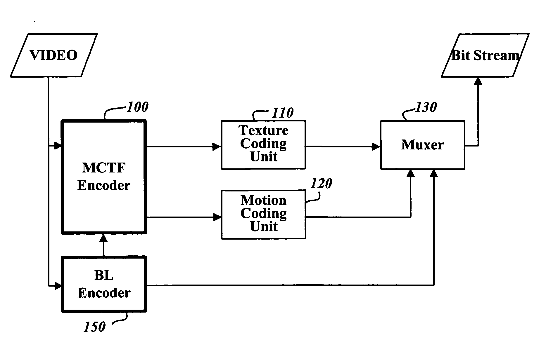
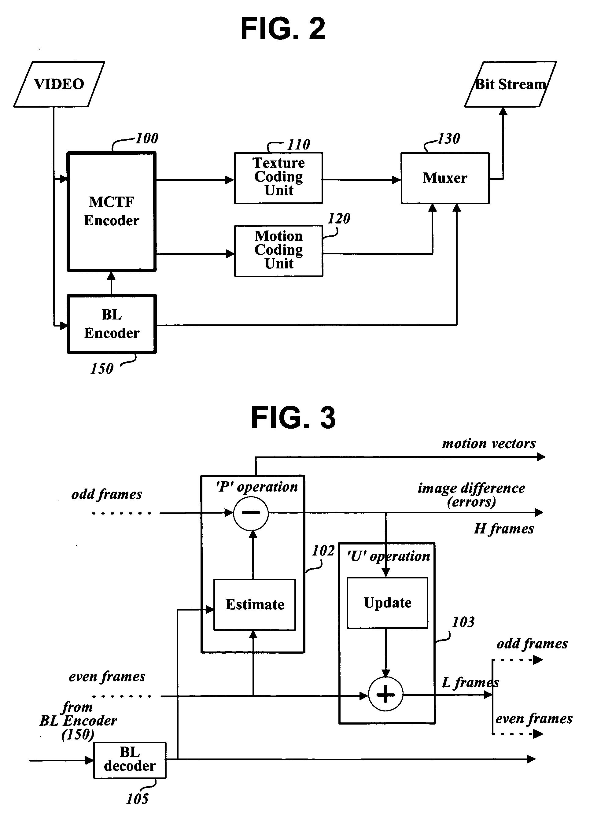
[0037]FIG. 2 is a block diagram of a video signal encoding apparatus to which a scalable video signal coding method according to the present invention is applied.

[0038] The video signal encoding apparatus shown in FIG. 2 comprises an MCTF encoder 100, a texture coding unit 110, a motion coding unit 120, a base layer encoder 150, and a muxer (or multiplexer) 130. The MCTF encoder 100 encodes an input video signal in units of macroblocks in an MCTF scheme, and generates suitable management information. The texture coding unit 110 converts information of encoded macroblocks into a compressed bitstream. The motion coding unit 120 codes motion vectors of image blocks obtained by the MCTF encoder 100 into a compressed bitstream according to a specified scheme. The base layer encoder 150 encodes an input video signal according to a specified scheme, for exampl...


PUM


Abstract

A method and apparatus for encoding video signals of a main layer using motion vectors of predictive image frames of an auxiliary layer and decoding such encoded video data is provided. In the encoding method, a video signal is encoded in a scalable MCTF scheme to output an enhanced layer (EL) bitstream and encoded in another specified scheme to output a base layer (BL) bitstream. During MCTF encoding, information regarding a motion vector of an image block in an arbitrary frame in a frame sequence of the video signal is recorded using a motion vector of a block, which is present, at a position corresponding to the image block, in an auxiliary frame present in the BL bitstream and temporally separated from the arbitrary frame. Using the correlation between motion vectors of temporally adjacent frames in different layers reduces the amount of coded motion vector data.

Description

PRIORITY INFORMATION [0001] This application claims priority under 35 U.S.C. §119 on Korean Patent Application No. 10-2005-0026796, filed on Mar. 30, 2005, and Korean Patent Application No. 10-2005-0026780, filed on Mar. 30, 2005, the entire contents of which are hereby incorporated by reference. [0002] This application also claims priority under 35 U.S.C. §119 on U.S. Provisional Application No. 60 / 631,177, filed on Nov. 29, 2004; U.S. Provisional Application No. 60 / 643,162, filed on Jan. 13, 2005, and U.S. Provisional Application No. 60 / 648,422. filed on Feb. 1, 2005, the entire contents of which are hereby incorporated by reference.BACKGROUND OF THE INVENTION [0003] 1. Field of the Invention [0004] The present invention relates to scalable encoding and decoding of video signals, and more particularly to a method and apparatus for encoding a video signal in a scalable Motion Compensated Temporal Filtering (MCTF) scheme using motion vectors of pictures of a base layer, and a method...

Claims


Application Information

Patent Timeline
Patent Type & Authority Applications(United States)
IPC IPC(8): H04N11/02H04N11/04H04N7/12H04B1/66
CPCH04N19/52H04N19/176H04N19/513H04N19/13H04N19/63H04N19/615H04N19/61H04N19/152H04N19/33H04N19/31H04N19/577H04N19/102
Inventor PARK, SEUNG WOOKPARK, JI HOJEON, BYEONG MOON
Owner LG ELECTRONICS INC
Why Eureka
Try Eureka