Electrical connector with support element

Inactive Publication Date: 2006-06-08
HON HAI PRECISION IND CO LTD
View PDF6 Cites 16 Cited by
  • Summary
  • Abstract
  • Description
  • Claims
  • Application Information

AI Technical Summary

Benefits of technology

[0008] An object of the invention is to provide

Problems solved by technology

It is the disadvantage of the electrical connector that too much space of an electrical device are occupied by the insulative housing.
This art does not provide an insulative housing.
However, assembling the camera m

Method used


Image

  • Electrical connector with support element
  • Electrical connector with support element
  • Electrical connector with support element

Examples


Example

[0020] Reference will now be made to the drawing figures to describe the present invention in detail.

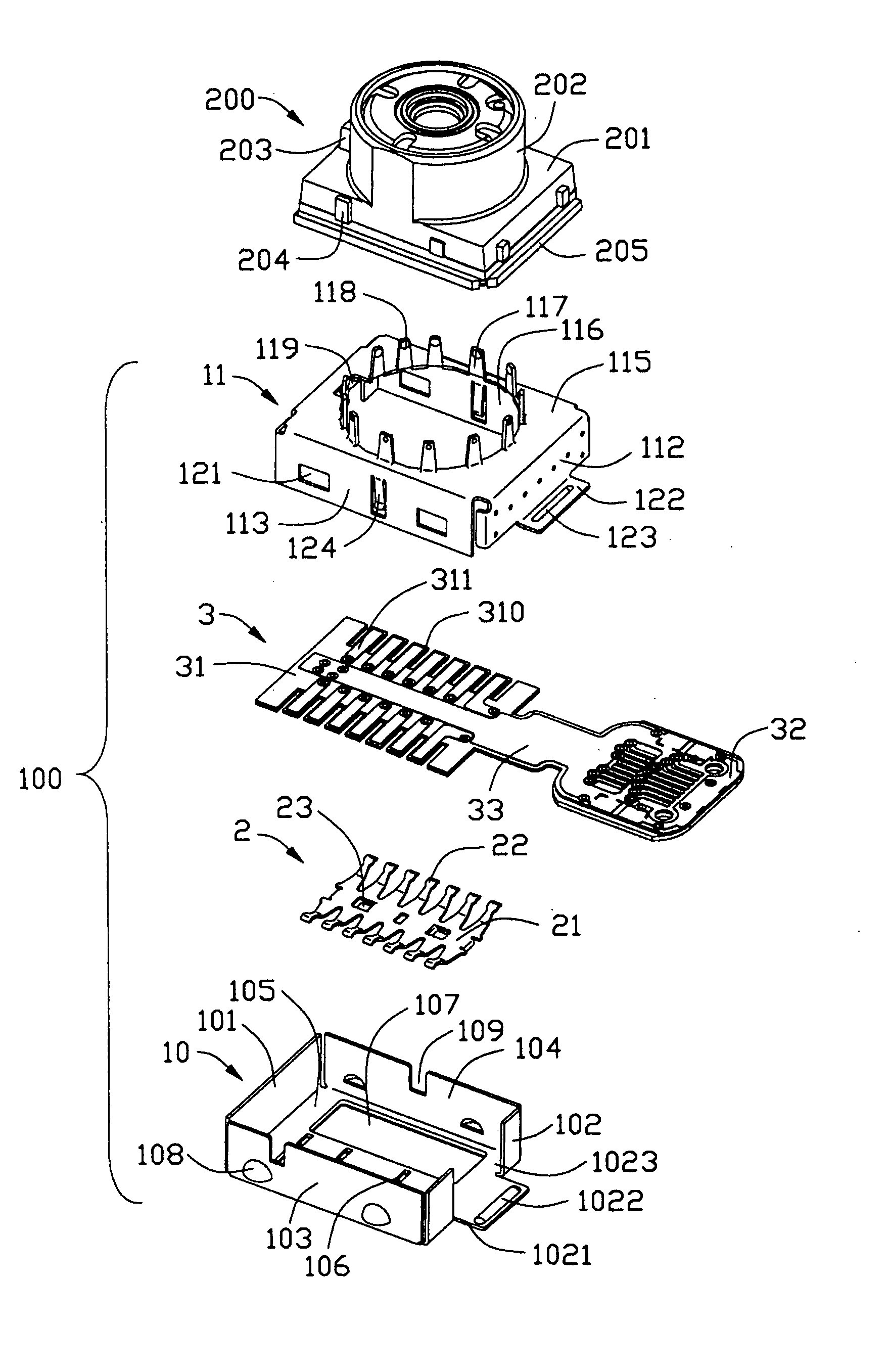
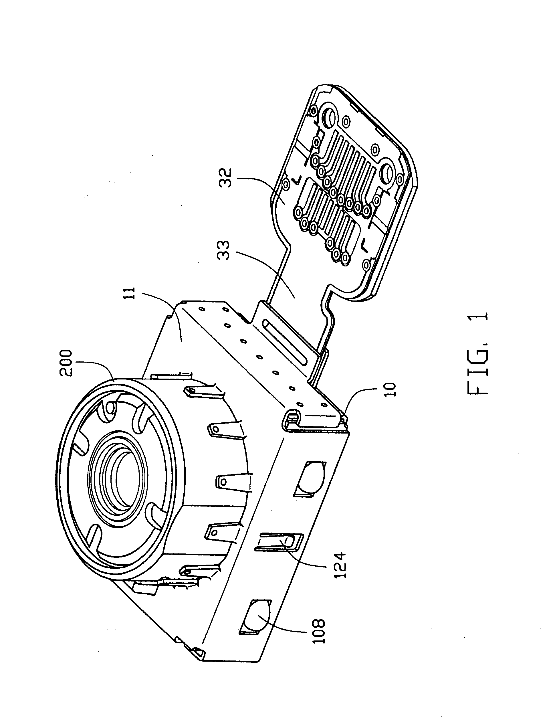
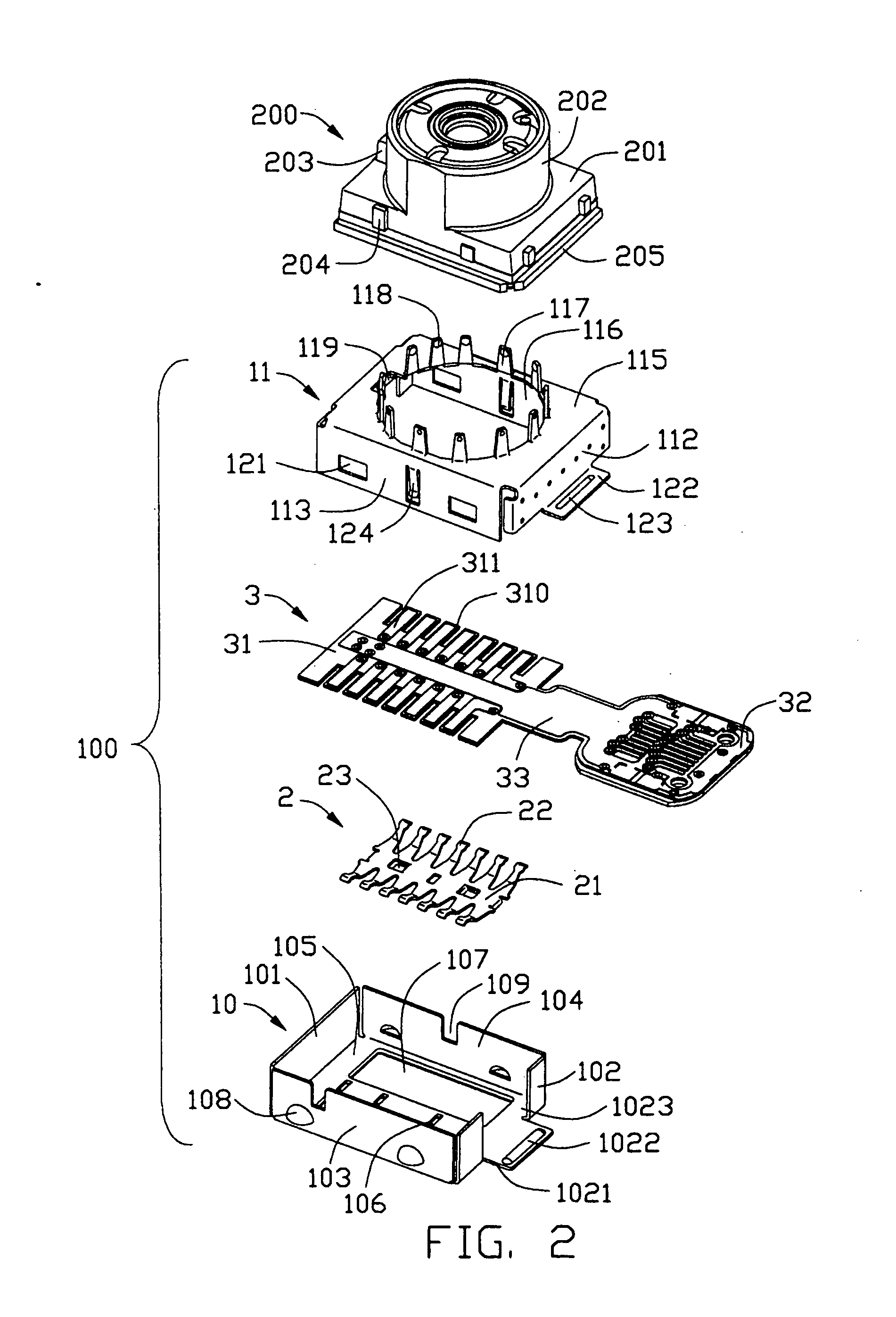
[0021] Referring to FIGS. 1, 2, and 3, an electrical connector 100 comprises a lower shield 10, an upper shield 11, a support element 2 and an FPC (Flexible Printed Circuit) 3. The connector 100 is adapted for receiving a camera module 200 therein. In an alternative embodiment, the electrical connector 100 may receive a memory module or the likes.

[0022] The lower shield 10 is substantially rectangular case, comprising a bottom wall 105 and four lateral walls 101, 102, 103, 104 extending upwardly from the bottom wall 105 to thereby define a rectangular receiving space (not labeled) therebetween. In an alternative embodiment, the receiving space also takes a circular shape, a quadrate shape or anther shape. The bottom wall 105 has four through holes 106 paralleled with each other defined on a central portion thereof and a pair of recesses 107 respectively defined on both sides of the...


PUM


Abstract

An electrical connector for receiving a module (200) includes a shield (10, 11) defining a receiving space (104) for receiving the module, an FPC (3) received in the receiving space for electrically connecting the module and a support element connected to the FPC for maintaining an electrical connection between the FPC and the module.

Description

BACKGROUND OF THE INVENTION [0001] 1. Field of the Invention [0002] The present invention relates to an electrical connector, and more particularly to an electrical connector for mounting a camera module. [0003] 2. Description of the Prior Art [0004] With development of cellular mobile phones or the likes, a lot of additional functions such as taking pictures etc. are added to the mobile phones or the likes. In order to achieve functions such as taking pictures etc., camera modules are furnished to the mobile phones or the likes in virtue of electrical connectors. [0005] An electrical connector for connecting a camera module to a circuit board is disclosed in US application No. 2004 / 0068868. Such electrical connector comprises a square insulative housing and a plurality of conductive terminals. The insulative housing comprises a plurality of receiving slots on inside wall for receiving the conductive terminals. The camera module is retained in the insulative housing and electrically...

Claims


Application Information

Patent Timeline
IPC IPC(8): H01R12/00
CPCH01R23/662H01R12/7076H01R13/6583H01R12/775H01R2201/16H01R12/00
Inventor KUO, WEI NANCHANG, JEN-JOU
Owner HON HAI PRECISION IND CO LTD
Why Eureka
Try Eureka