Moving-blade row for fluid-flow machines

a technology of moving blades and fluid-flow machines, which is applied in the direction of machines/engines, liquid fuel engines, reaction engines, etc., can solve the problems of low centrifugal force, and achieve the effect of preventing the vibration of moving blades

Inactive Publication Date: 2004-09-30
SIEMENS AG
View PDF12 Cites 16 Cited by
  • Summary
  • Abstract
  • Description
  • Claims
  • Application Information

AI Technical Summary

Benefits of technology

0012] The object of the present invention is to prevent the vibrations of a moving blade in a moving-blade row of a fluid-flow machine.

Problems solved by technology

The low mass of this supporting element leads to low centrifugal forces during operation.

Method used


Image

  • Moving-blade row for fluid-flow machines
  • Moving-blade row for fluid-flow machines
  • Moving-blade row for fluid-flow machines

Examples


Embodiment Construction

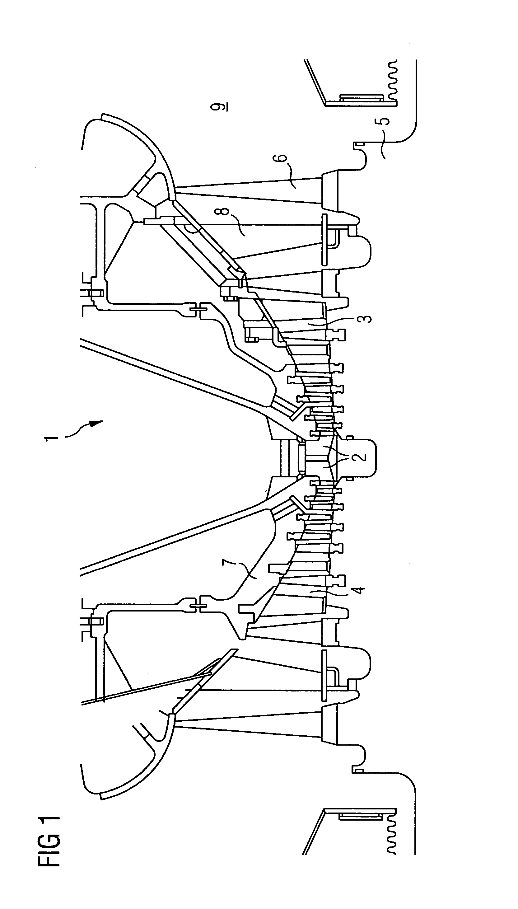
[0024] A partial cross section of a low-pressure steam turbine 1 is shown in FIG. 1. Via an inflow region 2, a flow medium flows through the flow passages 3, 4. A rotatably mounted rotor 5 has various moving-blade rows which are at a distance from one another in the axial direction and of which, for the sake of clarity, only one moving-blade row 6 is provided with a designation 6. Guide blades 8 are attached to an inner casing 7. The expanded steam passes out of the low-pressure steam turbine 1 via an outflow connection piece 9. In the process, the rotor 5 is moved in a rotary movement about a rotation axis 10.

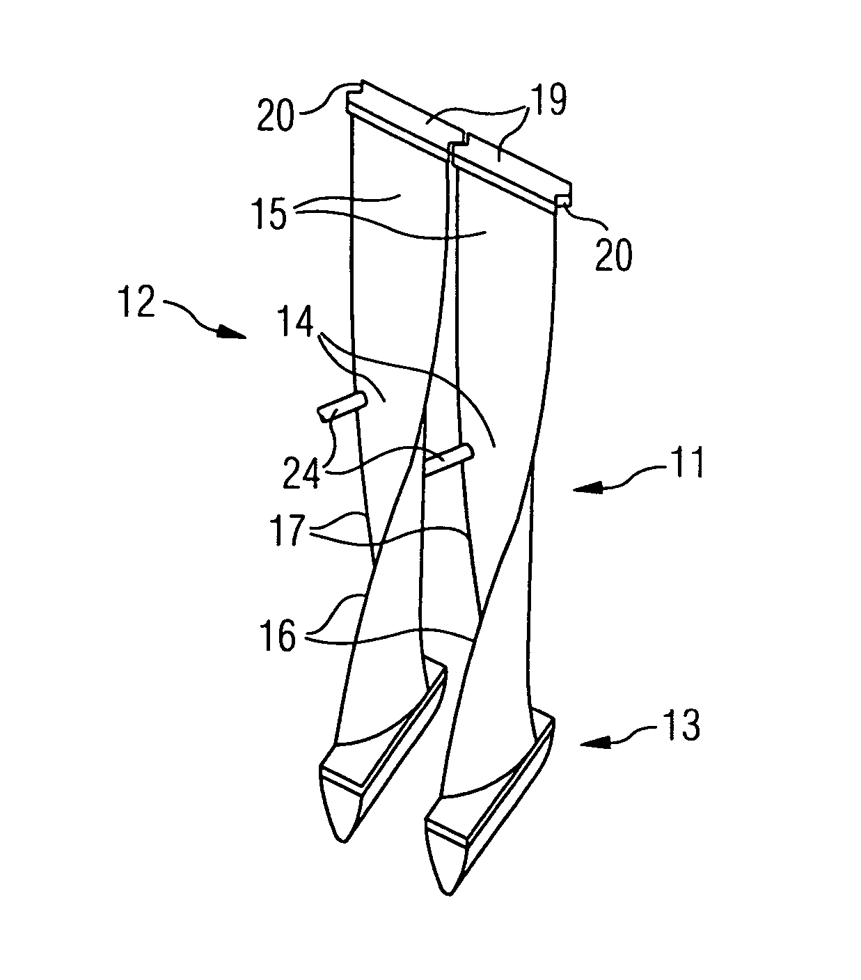
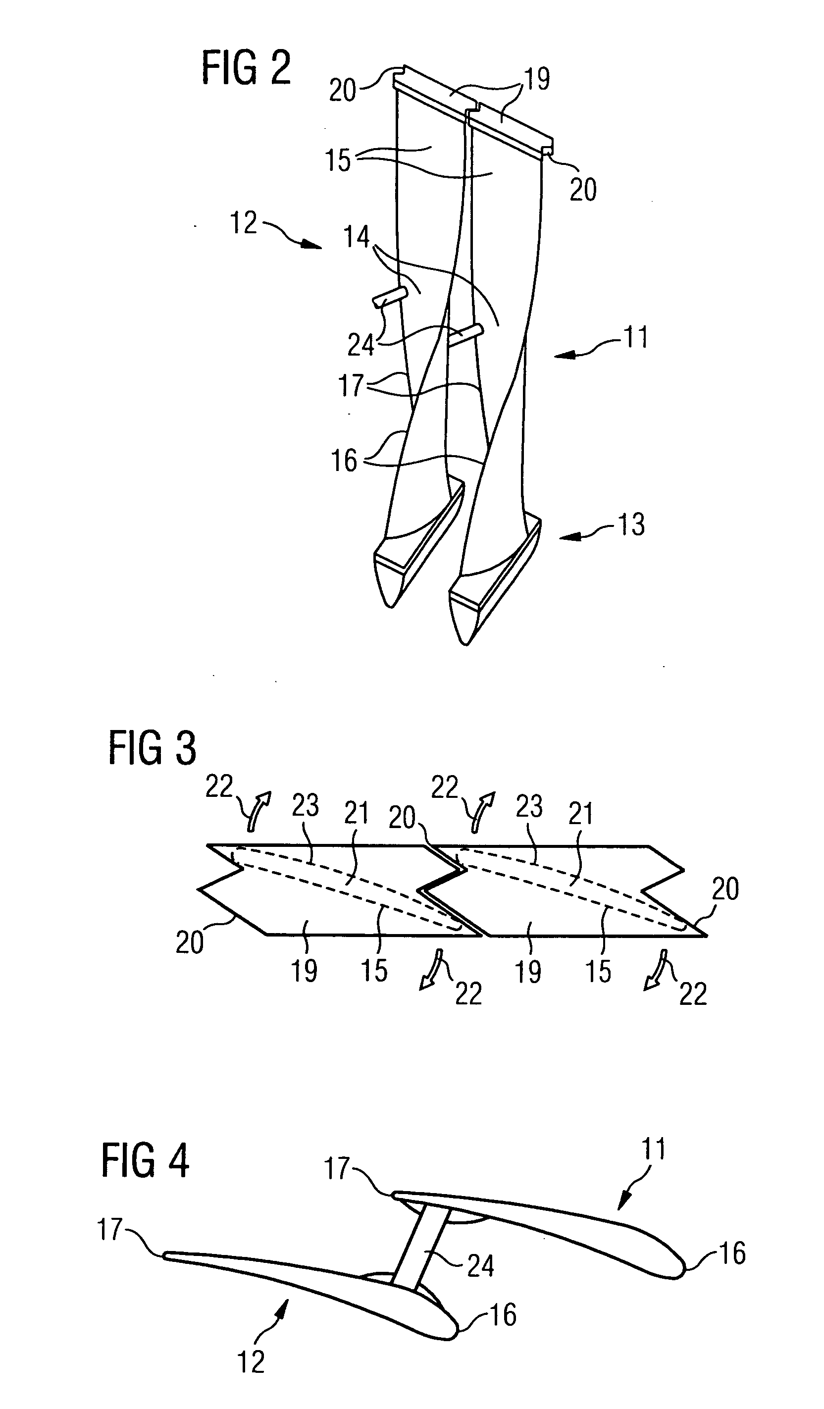
[0025] Two moving blades 11, 12 of a moving-blade row 6 are shown in FIG. 2. The moving blades 11, 12 have a moving-blade root 13, a moving-blade center region 14 and a moving-blade tip 15. Furthermore, the moving blades 11, 12 have a leading edge 16 and a trailing edge 17. Shroud plates 19 perpendicular to the radial orientation 18 of the moving blades 11, 12 are attached to ...


PUM

PropertyMeasurementUnit
lengthaaaaaaaaaa
pressureaaaaaaaaaa
centrifugal forcesaaaaaaaaaa

Abstract

The invention relates to a moving-blade row of a fluid-flow machine, the moving-blade row having individual adjacent moving blades which each have a moving-blade root and a moving-blade center region and also a moving-blade tip and a leading edge and a trailing edge, the moving blades being mechanically connected to one another in the moving-blade center region by supporting elements in such a way that undesirable vibrations of the moving blades are effectively avoided.

Description

[0001] This application claims priority of the European application No. 03007139.3 EP filed Mar. 28, 2003 under the European Patent Convention and which is incorporated by reference herein in its entirety.[0002] The invention relates to a moving-blade row of an axial turbine or of a compressor.BACKGROUND OF INVENTION[0003] In steam turbine construction, moving-blade rows which have a large incident-flow area are used in particular in the low-pressure region. The respective moving blades of such moving-blade rows are comparatively long in their radial direction. Such moving blades may have a length of over one meter. At the number of revolutions which can be achieved during operation, the centrifugal forces in the moving blades are so great that light material has to be used. Titanium or titanium alloy has proved successful in this respect and is frequently used nowadays in steam turbine construction. Due to the low density of titanium or titanium alloy, the centrifugal forces in mov...

Claims


Application Information

Patent Timeline
Patent Type & Authority Applications(United States)
IPC IPC(8): F01D5/22F01D5/24F01D5/28F01D25/00F04D29/38F04D29/66
CPCF05D2300/133F01D5/24
Inventor RICHTER, CHRISTOPHSTUER, HEINRICHTRUCKENMULLER, FRANK
Owner SIEMENS AG
Why Eureka
Try Eureka