

Rail transportation system powered by solar energy
A solar power supply and rail transit technology, applied in the field of rail transit system, can solve the problems of inability to realize manned and cargo operation, low conversion efficiency of solar panels, limited area of solar panels, etc., and achieve light weight, reduced installation space, and resource saving. Effect
- Summary
- Abstract
- Description
- Claims
- Application Information
AI Technical Summary
Problems solved by technology
Method used
Image

Examples
Embodiment 1
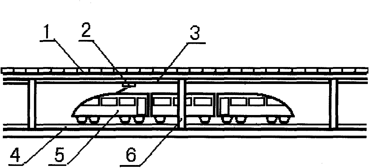
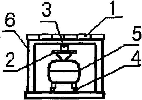
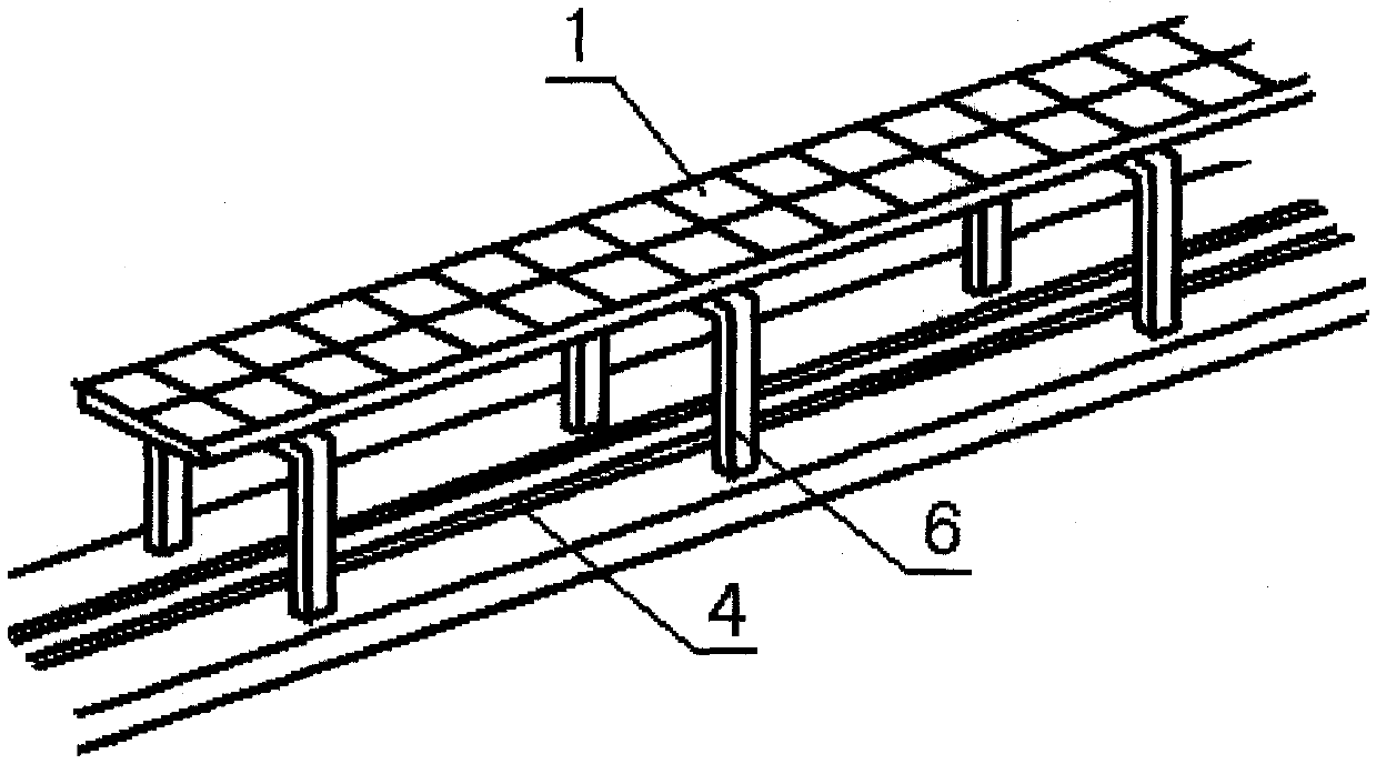
[0024] see figure 1 , as shown in the figure, the solar panel 1 is installed above the rail line 4 through the mounting frame 6, and the rail vehicle 5 running on the rail line contacts the power supply rail 3 installed on the mounting frame by the collector 2 above it to supply power for the vehicle . The track line adopts regional segmented independent power supply, that is, within a certain length range, the solar battery directly supplies power to the vehicle through the power supply rail; according to the current general solar battery, it can generate 0.2kw of power per square meter. Lay solar panels with a width of 3m, and the solar panels with an area of 3,000 square meters above every 1km line section can generate 600kw of power. According to the speed of rail vehicles at 120km per hour, the driving power of 1t of weight needs to be calculated at 3kw. Under these conditions, the power generated by each km of power supply section can theoretically fully satisfy a rai...
Embodiment 2
[0031] see image 3 , as shown in the figure, a collector compartment 10 is set on one side of the pure electric vehicle or dual-mode vehicle 7, and the collector 11 is installed in the collector compartment through a telescopic device or a folding device. When the vehicle enters the track system, the steel wheel 8 When running on the rail 4, the automatic control device opens the sealed cover of the collector compartment, and the collector protrudes from the collector compartment through the telescopic device or the retractable device, and contacts the power supply rail installed on the side of the mounting frame. Electric power is supplied to the vehicle, which drives the drive motor in the vehicle, which moves the vehicle through the rubber drive wheels that are still in contact with the road. As shown in the figure, when the steel wheel entered the rail operation, the rubber front wheel 9 broke away from the road surface.
[0032] In application, the steel wheel can be fi...
PUM
 Abstract
Description
Claims
Application Information