
Semiconductor-gated cardiac lead and method of use

Inactive Publication Date: 2006-06-08
CARDIAC PACEMAKERS INC
View PDF9 Cites 22 Cited by
  • Summary
  • Abstract
  • Description
  • Claims
  • Application Information

AI Technical Summary

Problems solved by technology

Such increased noise may result from increased sensing of myopotentials, electrical interference, or other interfering noise sources.
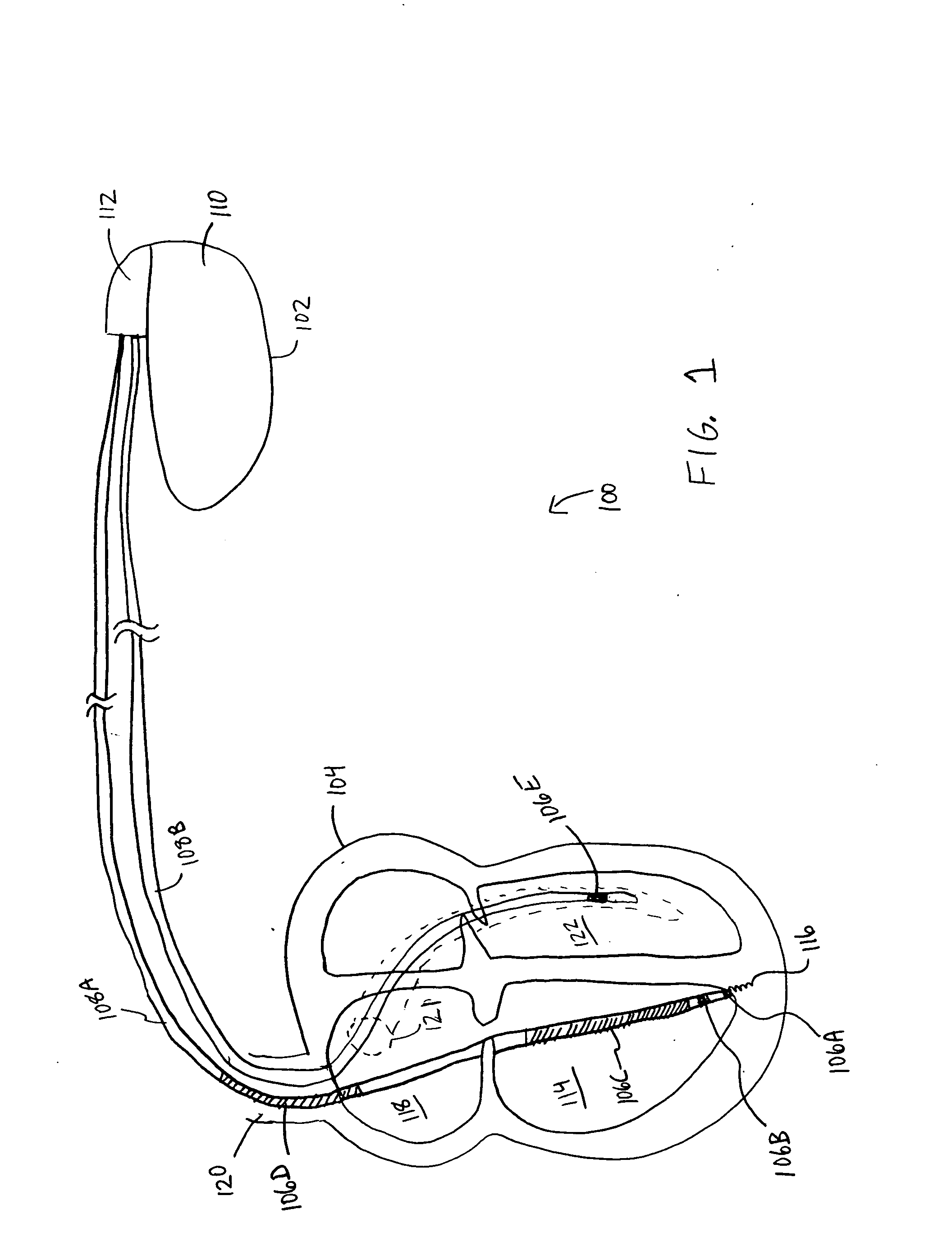
However, when the surface area of the return-path anode is too small, enough charge density can result at the anode to trigger an unintended anodic stimulation of the heart tissue.
This reduces the areal anodic charge density, which, in turn, reduces the likelihood of producing an unintended anodic stimulation of the heart tissue.
Unintended anodic stimulation is even a bigger problem when the two electrodes between which a pacing pulse is delivered are farther apart.
However, left-sided pacing (e.g., biventricular pacing) and certain other configurations may require increased pacing energy levels.
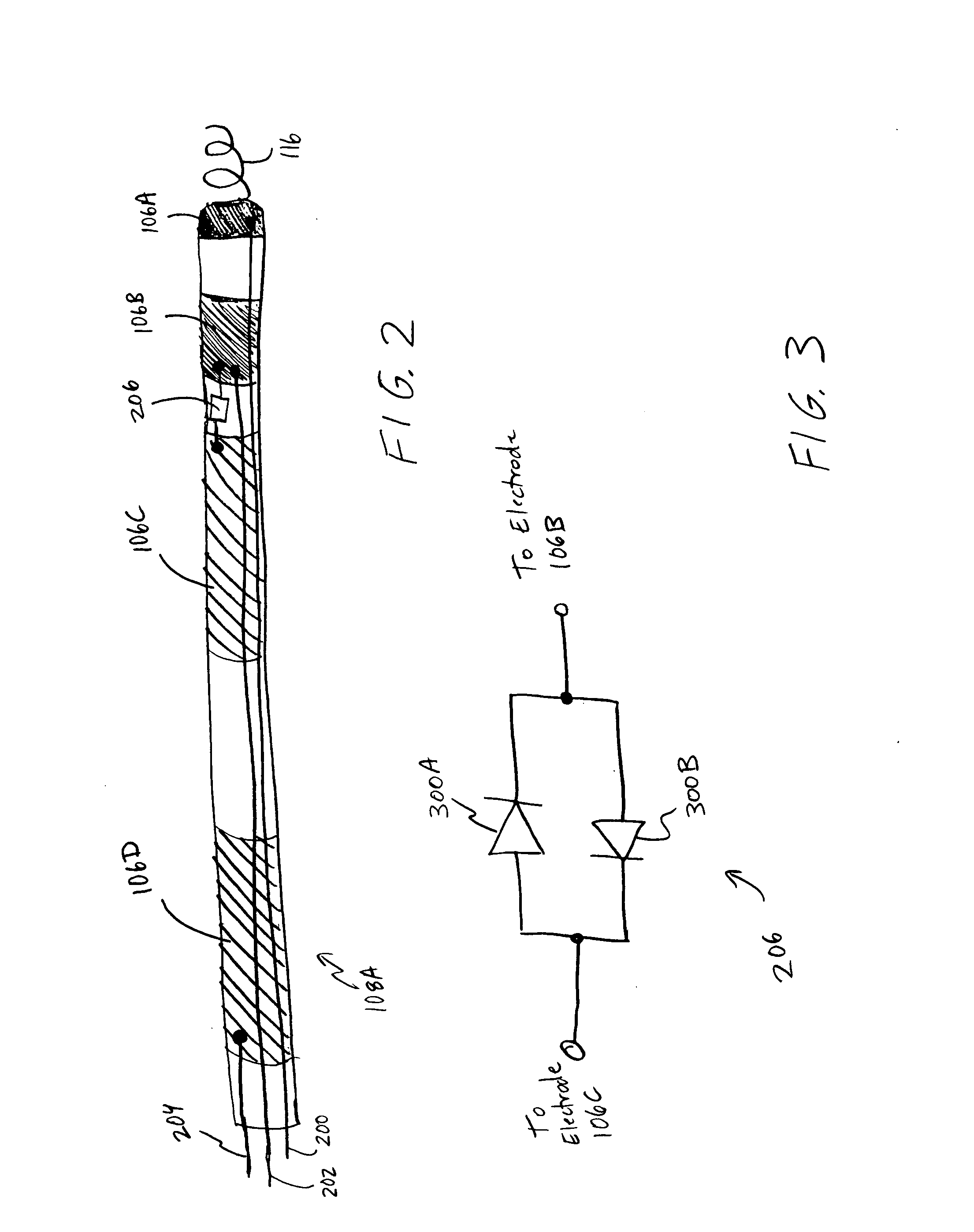
This larger energy may result in anodic stimulation at the ring electrode 106B, which could interfere with the desired spatial coordination of the left and right ventricular heart contractions.

Method used


Image

  • Semiconductor-gated cardiac lead and method of use
  • Semiconductor-gated cardiac lead and method of use
  • Semiconductor-gated cardiac lead and method of use

Examples


Embodiment Construction

[0011] The following detailed description includes references to the accompanying drawings, which form a part of the detailed description. The drawings show, by way of illustration, specific embodiments in which the invention may be practiced. These embodiments, which are also referred to herein as “examples,” are described in enough detail to enable those skilled in the art to practice the invention. The embodiments may be combined, other embodiments may be utilized, or structural, logical and electrical changes may be made without departing from the scope of the present invention. The following detailed description is, therefore, not to be taken in a limiting sense, and the scope of the present invention is defined by the appended claims and their equivalents.

[0012] In this document, the terms “a” or “an” are used, as is common in patent documents, to include one or more than one. In this document, the term “or” is used to refer to a nonexclusive or, unless otherwise indicated. F...


PUM


Abstract

This document discusses, among other things a cardiac lead with first and second electrodes electrically interconnected by back-to-back diodes or another conductivity control device. During sensing of intrinsic electrical heart signals, these electrodes are isolated from each other by the conductivity control device. This reduces noise during sensing. During pacing or defibrillation, these electrodes are electrically connected to each other by the conductivity control device. When used in common as a return path electrode, this avoids unintentional stimulation of the heart at the return path electrode instead of at the stimulating electrode. The electrodes can also share a common conductor from one of the electrodes back to a proximal end of the lead.

Description

TECHNICAL FIELD [0001] This patent document pertains generally to cardiac function management devices and more particularly, but not by way of limitation, to a semiconductor-gated cardiac lead and method of use. BACKGROUND [0002] Implantable medical devices include, among other things, cardiac function management (CFM) devices such as pacers, cardioverters, defibrillators, cardiac resynchronization therapy (CRT) devices, as well as combination devices that provide more than one of these therapy modalities to a subject. Such devices often include one or more diagnostic capabilities. Moreover, such diagnostic capabilities may be used as a basis for automatically providing therapy to the subject or for communicating diagnostic information to a physician or to the subject. [0003] One example of a diagnostic capability is sensing intrinsic electrical heart signals. These intrinsic heart signals include depolarizations that propagate through heart tissue. The depolarizations cause heart c...

Claims


Application Information

Patent Timeline
IPC IPC(8): A61N1/05
CPCA61N1/056A61N1/0563A61N1/0573A61N2001/0585
Inventor WENGREEN, ERIC JOHNHAMMILL, ERIC FALBEBABLER, LUKE THOMAS
Owner CARDIAC PACEMAKERS INC
Learn More