Lamp with protected combustion chamber

a technology of combustion chamber and lamp, which is applied in the field of lamps, can solve the problems of dangerous burning of candles and lamps that allow the flame to be exposed, and achieve the effect of preventing the burning of candles

Inactive Publication Date: 2006-06-15
WELCH TOMMY D
View PDF12 Cites 25 Cited by
  • Summary
  • Abstract
  • Description
  • Claims
  • Application Information

AI Technical Summary

Benefits of technology

[0006] The invention provides lamp configurations wherein a candle (oil or wax fueled) is burned inside a combustion chamber having a neck at defines the outlet to the chamber. The lamp prevents the candle from being blown out while also providing a safe housing for burning the candle.
[0007] The lamp provides configurations for efficiently distributing a scent when the lamp is burned. The lamp provides a variety of different locations where a scent such as a scented liquid may be held where it can be evaporated into the exhaust flow and distributed into the atmosphere surrounding the lamp.
[0011] A further configuration of the invention provides a candle wick holder that efficiently burns the wax of a candle by spreading the heat of the flame over a wider area to evenly melt a wide area of wax. The wick holder has a bowl-shaped base plate that defines an opening that allows the liquid wax to flow into the bowl where it contacts the wick. This wick holder may be used alone or in combination with the devices described above.

Problems solved by technology

Candles and lamps that allow the flame to be exposed can be dangerous.

Method used


Image

  • Lamp with protected combustion chamber
  • Lamp with protected combustion chamber
  • Lamp with protected combustion chamber

Examples


first embodiment

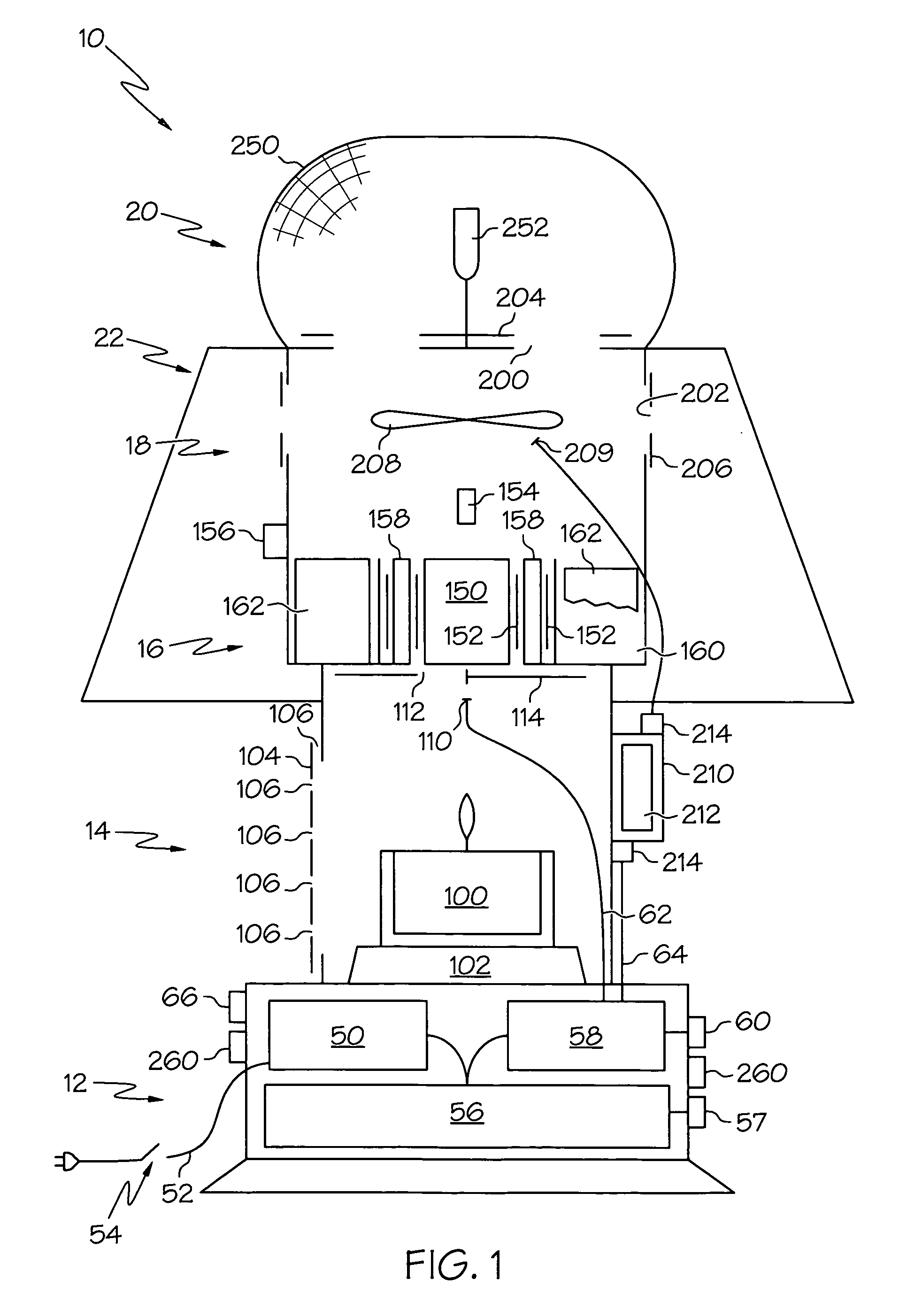
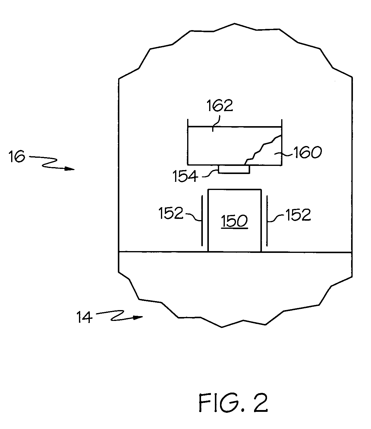
[0024] the insect killing device of the present invention is indicated generally by the numeral 10 in the accompanying drawings. In one embodiment, device 10 generally includes a control box 12, a combustion chamber 14, a catalyst chamber 16, a mixing chamber 18, a grid assembly 20, and an umbrella 22. Device 10 functions to lure bugs to device 10 and to kill bugs once they arrive. When used outside, device 10 uses carbon dioxide as the primary bait for the bugs. In addition, device 10 may use a scented bait to help lure the bugs. Device 10 may also use light sources to lure the bugs. Device 10 also uses heat to lure the bugs. When used inside to attract flies, device 10 relies on the scented bait, heat, and lights to attract the insects. Device 10 kills the bugs using at least one of an electrified grid and a sticky umbrella 22 that may be used alone or in combination.

[0025] Control box 12 generally includes a power supply 50, a power line 52, and a switch 54. Switch 54 allows the ...

second embodiment

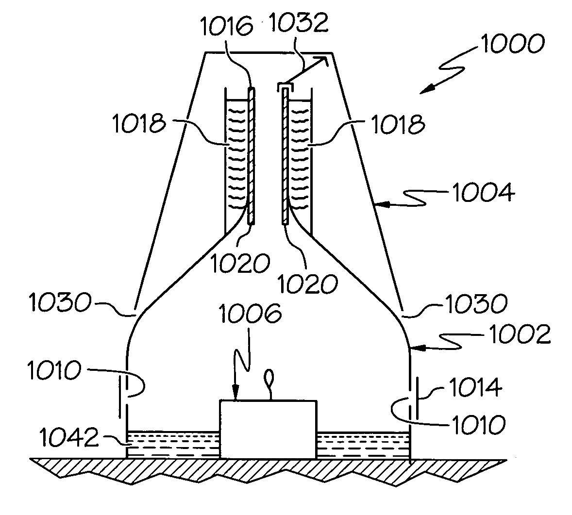
[0043] the insect killing device of the present invention is indicated generally by the numeral 500 in the accompanying drawings. In one embodiment, device 500 generally includes a control box 512, a combustion chamber 514, a cooling chamber 516, a mixing chamber 518, first and second grid assemblies 520,521 and an umbrella 522. Umbrella 522 protects first grid 520 while a cage 524 protects second grid 521. Cage 524 may also be sticky to catch bugs. Umbrella 522 may also protect device 500 from rain. Device 500 functions to lure bugs to device 500 and to kill bugs once they arrive. When used outside, device 500 uses carbon dioxide as the primary bait for the bugs. In addition, device 500 may use a scented bait to help lure the bugs. Device 500 may also use light sources to lure the bugs. Device 500 also uses heat to lure the bugs. When used inside to attract flies, device 500 relies on the scented bait, heat, and lights to attract the insects. Device 500 kills the bugs using at leas...


PUM


Abstract

A lamp includes a combustion chamber having a neck that defines a combustion chamber air outlet. A candle is disposed in the combustion chamber and, when burned, creates an upward flow of air and combustion products through the neck. A reservoir is disposed around a portion of the neck with a material to be heated disposed in the reservoir. In one configuration, the material is a candle fuel that is wicked by the neck and drips into the candle to refuel the candle. In another configuration, the material is a scented material that evaporates when heated to distribute the scent. A cooling chamber may be disposed above the combustion chamber with the outlet of the cooling chamber being disposed below the outlet of the neck. Another configuration allows the height of the flame to be adjusted by varying the volume of air allowed to be drawn into the unit.

Description

CROSS REFERENCE TO RELATED APPLICATIONS [0001] This application is a continuation-in-part application claiming priority from US application Ser. No. 11 / 013,776 which claims priority from U.S. Provisional Patent Application Ser. No. 60 / 529,816 filed Dec. 16, 2003; the disclosures of both are incorporated herein by reference.BACKGROUND OF THE INVENTION [0002] 1. Technical Field [0003] The present invention generally relates to lamps and, more particularly, to oil or wax powered lamps with structures that prevent the lamps from being extinguished in the wind while also providing protection against fires. Specifically, the present invention relates to lamps having such combustion chambers that are also adapted to efficiently distribute a scent into the air while the lamp burned. [0004] 2. Background Information [0005] Various wax and oil lamp structures are known in the art. Candles and lamps that allow the flame to be exposed can be dangerous. The art recognizes that surrounding the fl...

Claims


Application Information

Patent Timeline
Patent Type & Authority Applications(United States)
IPC IPC(8): A01M1/04A01M1/02A01M1/14A01M1/22
CPCA01M1/02A01M1/023A01M1/04A01M1/14A01M1/145A01M1/223A01M2200/012
Inventor WELCH, TOMMY D.
Owner WELCH TOMMY D
Why Eureka
Try Eureka