Polymerizable liquid crystal compound, liquid crystal composition and optical anisotropic material
- Summary
- Abstract
- Description
- Claims
- Application Information
AI Technical Summary
Benefits of technology
Problems solved by technology
Method used
Image

Examples
example 1
Preparation Example for Compound (1A-a3)
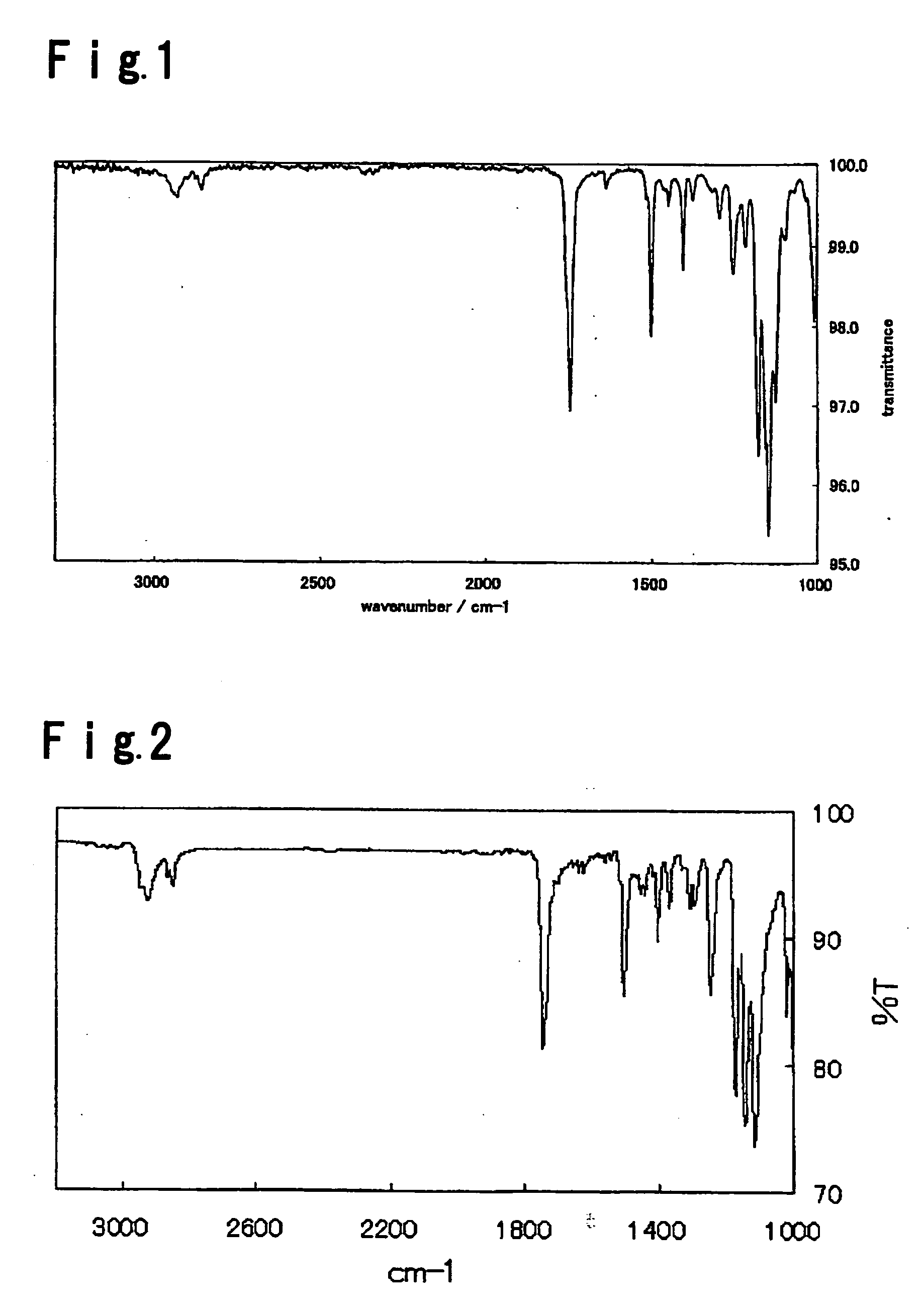
[0067]
[0068] Into a mixture of a compound (d-1) (4.4 g, 0.017 mol), dichloromethane (70 mL) and triethylamine (2.5 g, 0.025 mol), a compound (c) (2.7 g, 0.017 mol) was added under cooling with ice water so that the temperature of the reaction solution would not exceed 20° C. After stirring for 24 hours, a mixture of concentrated hydrochloric acid (2 mL), ice (20 g) and water (30 mL) was added to the reaction solution. An organic layer was separated, and a saturated sodium chloride aqueous solution (40 mL) was added thereto to carry out liquid separation. The organic layer was separated again and washed with water, and then dried over anhydrous magnesium sulfate, followed by filtration under reduced pressure.
[0069] The filtrate was purified by means of column chromatography (developing solvent: dichloromethane / toluene). The fraction containing the desired product was concentrated to obtain a crystal powder. To this crystal powder, a mixed sol...
example 2
Preparation Example for Compound (1A-a5)
[0073]
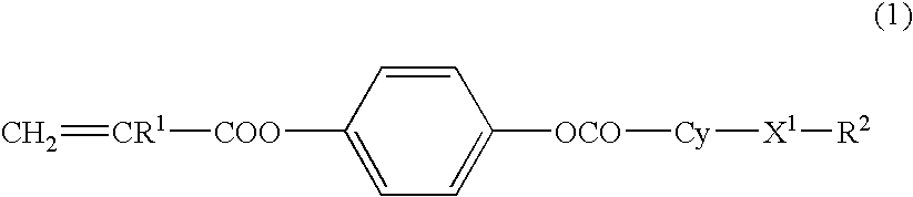
[0074] The reaction was carried out in the same manner as in Example 1 except that the compound (d-1) was changed to the following compound (d-2), to obtain a compound (1A-a5) (5.04 g). The yield was 70.5%.
[0075] The compound (1A-a5) had a transition temperature from crystal to a nematic phase of 72.3° C. and a transition temperature from a nematic liquid phase to an isotropic phase of 210.9° C. (extrapolation value). The infrared absorbance spectrum of the compound (1A-a5) is shown in FIG. 2. The result of measurement of the 1HNMR spectrum of the compound (1A-a5) is shown as follows.
[0076]1HNMR (solvent: CDCl3, internal standard: TMS) δ (ppm) 0.9 (triplet, 3H), 1.4-1.8 (m, 10H), 2.0-2.7 (Complex, m, 8H), 6.0-6.7 (m, 3H), 7.0-7.2 (s, 8H).
example 3
Example 3-1
Formulation Example(1) for Liquid Crystal Composition
[0077] The compound (1A-a3) obtained in Example 1 and the following compound (2-5) were mixed in a ratio of 1:1 (molar ratio) to prepare a liquid crystal composition A.
CH2═CHCOO-Ph-OCO-Cy-C5H11 (2-5)
[0078] The liquid crystal composition A showed a nematic phase in a range of from room temperature to a super cooling state. Further, the phase transition temperature from the nematic phase to an isotropic phase was at least 154° C.
[0079] Then, a photopolymerization initiator was added to the liquid crystal compositions A in proportions of 0.5 mass % and 1.0 mass % to such liquid crystal compositions A to obtain a liquid crystal composition Al and a liquid crystal composition A2, respectively.
PUM
| Property | Measurement | Unit |
|---|---|---|
| Percent by mass | aaaaa | aaaaa |
| Composition | aaaaa | aaaaa |
| Light | aaaaa | aaaaa |
Abstract
Description
Claims
Application Information
 - R&D Engineer
- R&D Manager
- IP Professional
- Industry Leading Data Capabilities
- Powerful AI technology
- Patent DNA Extraction
Browse by: Latest US Patents, China's latest patents, Technical Efficacy Thesaurus, Application Domain, Technology Topic.
© 2024 PatSnap. All rights reserved.Legal|Privacy policy|Modern Slavery Act Transparency Statement|Sitemap