Bumper structure for a motor vehicle

Inactive Publication Date: 2006-06-15
BENTELER AUTOMOBILTECHNIK GMBH
View PDF4 Cites 17 Cited by
  • Summary
  • Abstract
  • Description
  • Claims
  • Application Information

AI Technical Summary

Benefits of technology

[0010] The present invention resolves prior art problems by directly securing the crash box to the longitudinal member without intervention of flanged plates. This results in desired weight saving. The crash box is constructed for nominal spacing in relation to the cross section profile of the longitudinal member so as to be securable to the longitudinal member in the presence of encountered tolerances by undergoing, at least locally, an elastic or plastic deformation. The fastening means, e.g. bolts, for securing the attachment zone of the crash box to the longitudinal member bridge hereby a generously sized tolerance distance between the walls of the attachment zone and longitudinal member and urge the wall of the crash box against the wall of the longitudinal member. During assembly, the cross member assumes jointly with the crash box a predefined position which is precisely maintained as the crash box self-centers in relation to the longitudinal member. Self-centering eliminates the need for oblong holes that are difficult to produce in the longitudinal member or in crash boxes. As a result of the particular configuration of the attachment zone, which is able to locally undergo an elastic or plastic deformation during installation, the spatial position of the crash box remains unchanged as the bolts are tightened. The tolerance distance between the walls of the attachment zone and the longitudinal member is intentionally dimensioned greater than would be possible to manufacture so as to permit a slight transverse movement of the cross member with crash boxes transversely to the vehicle length axis. The crash box can be firmly mounted to the cross member. No complicated adjustments in the attachment zone between the crash box and the cross member are thus required. This, too, reduces weight and simplifies installation. A bumper according to the present invention comprised of the cross member with accommodated crash boxes can thus form a very lightweight structure which can be easily and rapidly assembled.
[0011] According to another feature of the present invention, the crash box may be comprised of two half-shells which are connected to one another only in an area outside the attachment zone. In other words, the half-shells are not joined in the area of the attachment zone. As a result, the half-shells can easily be deformed relative to one another in the area of the attachment zone. Thus, stress peaks are slight, and the torque to tighten the bolts is low so that the installation is simple.
[0012] When the crash box is of single-piece configuration, for example in the form of a hollow section, length slots may be formed in the wall of the attachment zone so as to define attachment tongues to thereby provide the wall with elastic or plastic deformation capability. Of course, crash boxes, made by joining half-shells, may be formed with length slots as well to enhance elasticity and thus attachment capability to the longitudinal member. The length slots extend to the end surfaces of the attachment zone and may be provided in particular in a corner area of the crash box. Thus, a rectangular profile for example, may have four independently deformable attachment tongues which can be urged against the wall of the longitudinal member to bridge the predefined tolerance distance, without adversely affecting the other attachment tongues.
[0014] According to another feature of the present invention, the half-shells of the crash box may have marginal webs which are connected to one another to define flanges and the longitudinal member may be made of two half-shells which also have marginal webs connected to one another to define flanges. In this case, the webs of the crash box extend in the attachment zone at a distance to one another and surround the flanges of the longitudinal member with the tolerance distance. The webs of the crash box embrace hereby the flanges of the longitudinal member, while maintaining the tolerance distance. When a desired assembly position has been realized, the bolts which extend through the flanges of the longitudinal member and the webs of the crash boxes can be tightened to center the crash box in relation to the longitudinal member. The spaced-apart webs of the crash box thus serve quasi as length slot in the attachment zone so that the half-shells of the crash box become more flexible and easier to deform in the attachment zone with the longitudinal member.
[0015] According to another feature of the present invention, the cross member may have a hat-shaped cross section with a center plate which is recessed in a direction of the crash box and terminates in angled legs, wherein the half-shells of the crash box have marginal webs which are connected to one another to define flanges for connection to the legs. The attachment of the crash box to the cross member is thus realized also via the marginal webs and not via box-shaped center parts of the crash box. The hat-shaped profile enhances bending resistance of the cross member and extends therefore typically over the entire length of the cross member. Unlike the support of box-shaped center parts of crash boxes on the center webs of the cross member, the webs of the crash boxes according to the present invention extend beyond the end surfaces of their respective center parts up to the legs so that the legs provide additional reinforcement and support that positively affects the deformation behavior of the crash box. The flange in the shape of a shell construction of the crash box is suitably welded to the cross member. The need for additional sheet-metal bulkheads is eliminated.

Problems solved by technology

Like the afore-described support of the crash boxes on the end surface of the longitudinal members, this construction too requires increased installation space.

Method used


Image

  • Bumper structure for a motor vehicle
  • Bumper structure for a motor vehicle
  • Bumper structure for a motor vehicle

Examples


Embodiment Construction

[0023] Throughout all the Figures, same or corresponding elements are generally indicated by same reference numerals. These depicted embodiments are to be understood as illustrative of the invention and not as limiting in any way. It should also be understood that the drawings are not necessarily to scale and that the embodiments are sometimes illustrated by graphic symbols, phantom lines, diagrammatic representations and fragmentary views. In certain instances, details which are not necessary for an understanding of the present invention or which render other details difficult to perceive may have been omitted.

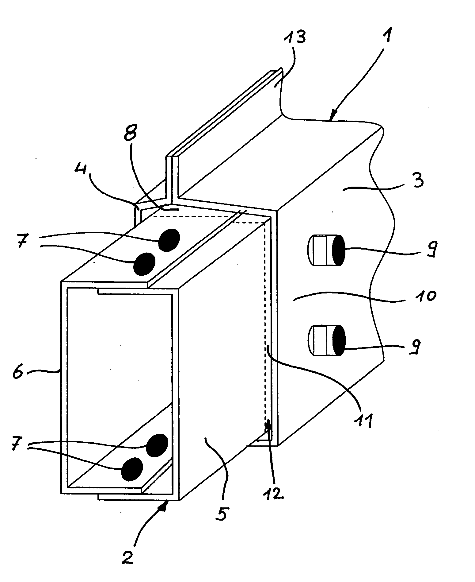
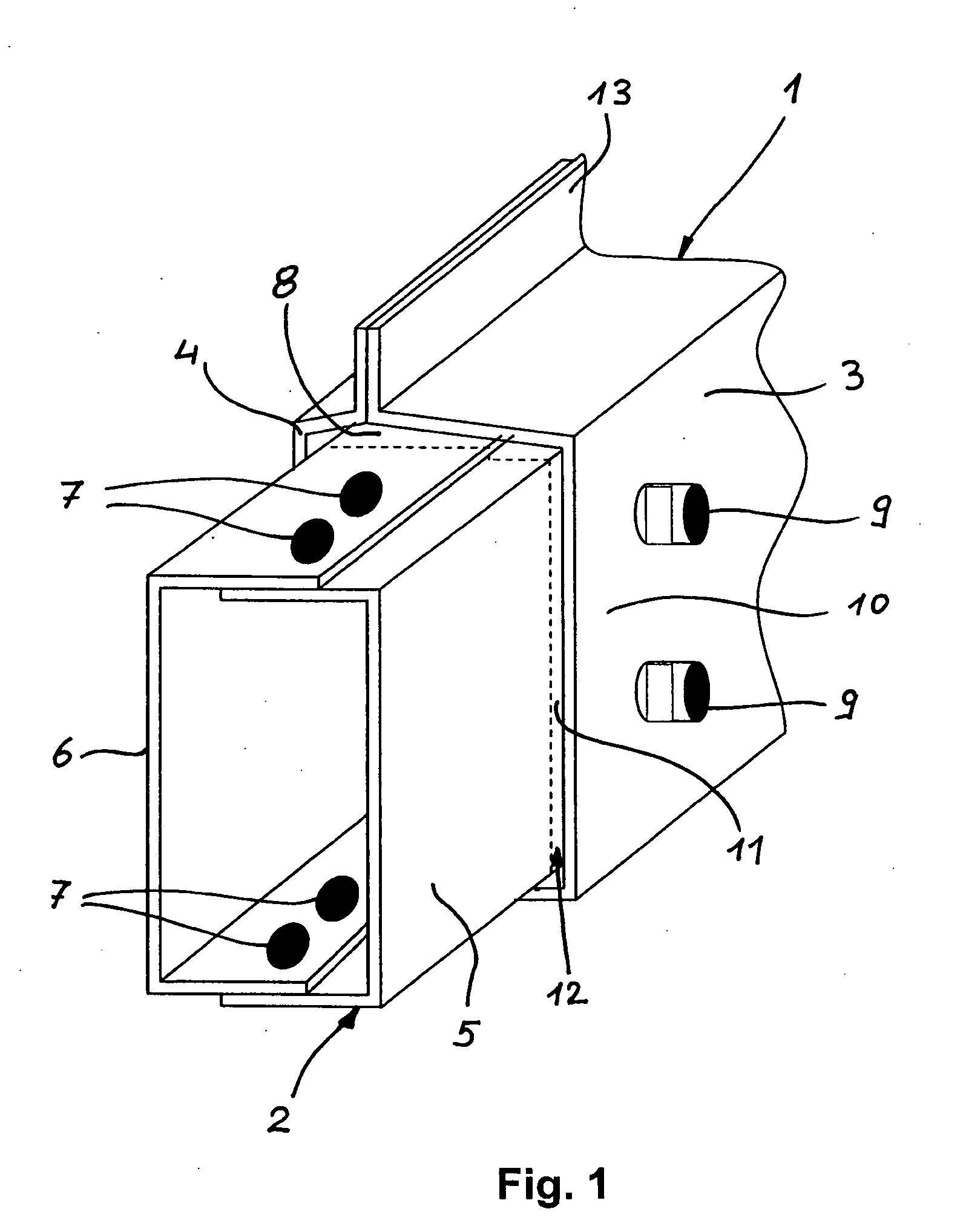
[0024] Turning now to the drawing, and in particular to FIG. 1, there is shown a perspective view of a longitudinal member 1 of an otherwise unillustrated motor vehicle in connection with a crash box 2 of a bumper structure according to the present invention. The longitudinal member 1 as well as the crash box 2 is manufactured in the shape of a shell construction. The longit...


PUM


Abstract

A bumper structure for a motor vehicle includes a cross member, and a crash box placed between the cross member and a longitudinal member, with the crash box having an attachment zone. Bolts extend through walls of the attachment zone and the longitudinal member for securing the crash box to the longitudinal member by forcing the attachment zone against the wall of the longitudinal member. The attachment zone undergoes hereby locally an elastic or plastic deformation for realizing a self-centered disposition of the crash box in relation to the longitudinal member. The walls of the attachment zone and the longitudinal member extend at a tolerance distance before the crash box is secured to the longitudinal member.

Description

CROSS-REFERENCES TO RELATED APPLICATIONS [0001] This application claims the priority of German Patent Application, Serial No. 10 2004 060 088.0, filed Dec. 13, 2004, pursuant to 35 U.S.C. 119(a)-(d), the subject matter of which is incorporated herein by reference. BACKGROUND OF THE INVENTION [0002] The present invention relates, in general, to a bumper structure for a motor vehicle. [0003] Nothing in the following discussion of the state of the art is to be construed as an admission of prior art. [0004] A standard bumper structure is typically mounted on the front or rear of a motor vehicle between the plastic shell construction, which encloses the vehicle body, and the body-supporting structure or chassis of the motor vehicle, and includes a cross member for connection to two longitudinal members of the chassis. To prevent damage to the vehicle structure in the event of a frontal or rear impact at low speed, crumpling or deformation elements, called crash boxes, are arranged betwee...

Claims


Application Information

Patent Timeline
IPC IPC(8): B60R19/56B60R19/04
CPCB60R19/34B60R2019/245
Inventor ARNS, WILHELMROTZOLL, SVEN-LARS
Owner BENTELER AUTOMOBILTECHNIK GMBH
Why Eureka
Try Eureka