Exposure apparatus and method for producing device

a technology of producing device and exposure apparatus, which is applied in the direction of photomechanical apparatus, printing, instruments, etc., can solve the problems of deterioration of pattern images to be formed on the substrate, insufficient margin, and difficulty in matching the substrate surface with respect to the image plane of the projection optical system, etc., to suppress the productivity decline and suppress the productivity decline.

Inactive Publication Date: 2006-06-15
NIKON CORP
View PDF56 Cites 120 Cited by
  • Summary
  • Abstract
  • Description
  • Claims
  • Application Information

AI Technical Summary

Benefits of technology

[0012] The present invention has been made taking the foregoing circumstances into consideration, an object of which is to provide an exposure apparatus which makes it possible to suppress the decrease in productivity even when the liquid immersion method is used, and a method for producing a device based on the use of the exposure apparatus. Another object of the present invention is to provide an exposure apparatus which makes it possible to detect, for example, any deterioration of a pattern image caused by any bubble in a liquid when the exposure process is performed while filling the space between a projection optical system and a substrate with the liquid, and a method for producing a device based on the use of the exposure apparatus. Still another object of the present invention is to provide an exposure apparatus which makes it possible to suppress the decrease in productivity caused by the fact that the space between a projection optical system and a substrate is not filled with a liquid, and a method for producing a device based on the use of the exposure apparatus. Still another object of the present invention is to provide an exposure apparatus which makes it possible to suppress the occurrence of, for example, any exposure failure and / or any measurement failure even when the liquid immersion method is used, and a method for producing a device based on the use of the exposure apparatus.
[0017] According to the present invention, when the exposure process is performed on the basis of the liquid immersion method, the bubble is detected in the liquid between the projection optical system and the substrate by the aid of the bubble detector. Accordingly, it is possible to detect the information about the bubble in the liquid between the projection optical system and the substrate, as the portion which greatly concerns the pattern transfer accuracy. The exposure failure (defective shot) can be recognized on the basis of the result of the detection. Therefore, it is possible to apply an appropriate treatment in order to maintain the high device productivity.
[0021] According to the present invention, when the exposure process is performed on the basis of the liquid immersion method, it is possible to detect whether or not the liquid, with which the space between the projection optical system and the substrate is filled, is insufficient, by the aid of the liquid shortage detector. Therefore, it is possible to recognize, at an early stage, the occurrence of the exposure failure and the defective shot on the basis of the result of the detection. It is possible to apply an appropriate treatment in order not to produce any defective device which would be otherwise produced due to the liquid shortage. For example, when any water shortage is detected, the exposure is performed after solving the water shortage. Thus, it is possible to suppress the occurrence of the exposure failure and the defective shot.
[0024] According to the present invention, the gas-detecting system is used to detect the presence or absence of the gas portion in the optical path for the exposure light beam. Accordingly, for example, it is possible to recognize whether or not any defective shot or any image formation failure of the pattern image appears resulting from the gas portion during the exposure for the substrate. Accordingly, it is possible to apply an appropriate treatment in order to maintain the high device productivity. The exposure can be started for the substrate after confirming the fact that the gas portion is absent in the optical path for the exposure light beam. Therefore, it is also possible to suppress the production of any defective device.
[0028] According to the present invention, the surface position-detecting system, which detects the surface position information about the substrate through the liquid, is used to detect the presence or absence of the gas portion in the optical path for the detecting light beam. Accordingly, for example, it is possible to recognize whether or not any defective shot or any image formation failure of the pattern image appears resulting from the gas portion during the exposure for the substrate. Accordingly, it is possible to apply an appropriate treatment in order to maintain the high device productivity. When the surface position-detecting system is used also as the gas-detecting system for detecting the presence or absence of the gas portion, it is possible to detect the presence or absence of the gas portion without complicating the arrangement of the apparatus.

Problems solved by technology

If the depth of focus δ is too narrowed, it is difficult to match the substrate surface with respect to the image plane of the projection optical system.
It is feared that the margin is insufficient during the exposure operation.
When the exposure process is performed by the liquid immersion method, if any gas portion such as bubbles or the like exists in the liquid (especially on the substrate surface) between the projection optical system and the substrate, it is feared that a pattern image to be formed on the substrate may be deteriorated by the influence of the bubble (gas portion).
If the image formation failure of the pattern image as described above is left as it is, the failure is consequently found out as a defective product at the stage at which the final device is produced.
It is feared that the device productivity may be lowered.
In this situation, there is such a possibility that the pattern image may not be formed on the substrate.
If such a situation is left as it is, then it is impossible to found out the defect until the final device is produced, and it is feared that the productivity may be lowered.
However, if the gas portion exists on the image plane side of the projection optical system, and the space is not filled with a sufficient amount of the liquid, then there is such a possibility that the measurement error appears, and / or it is impossible to perform the measurement in some situations.

Method used


Image

  • Exposure apparatus and method for producing device
  • Exposure apparatus and method for producing device
  • Exposure apparatus and method for producing device

Examples


Embodiment Construction

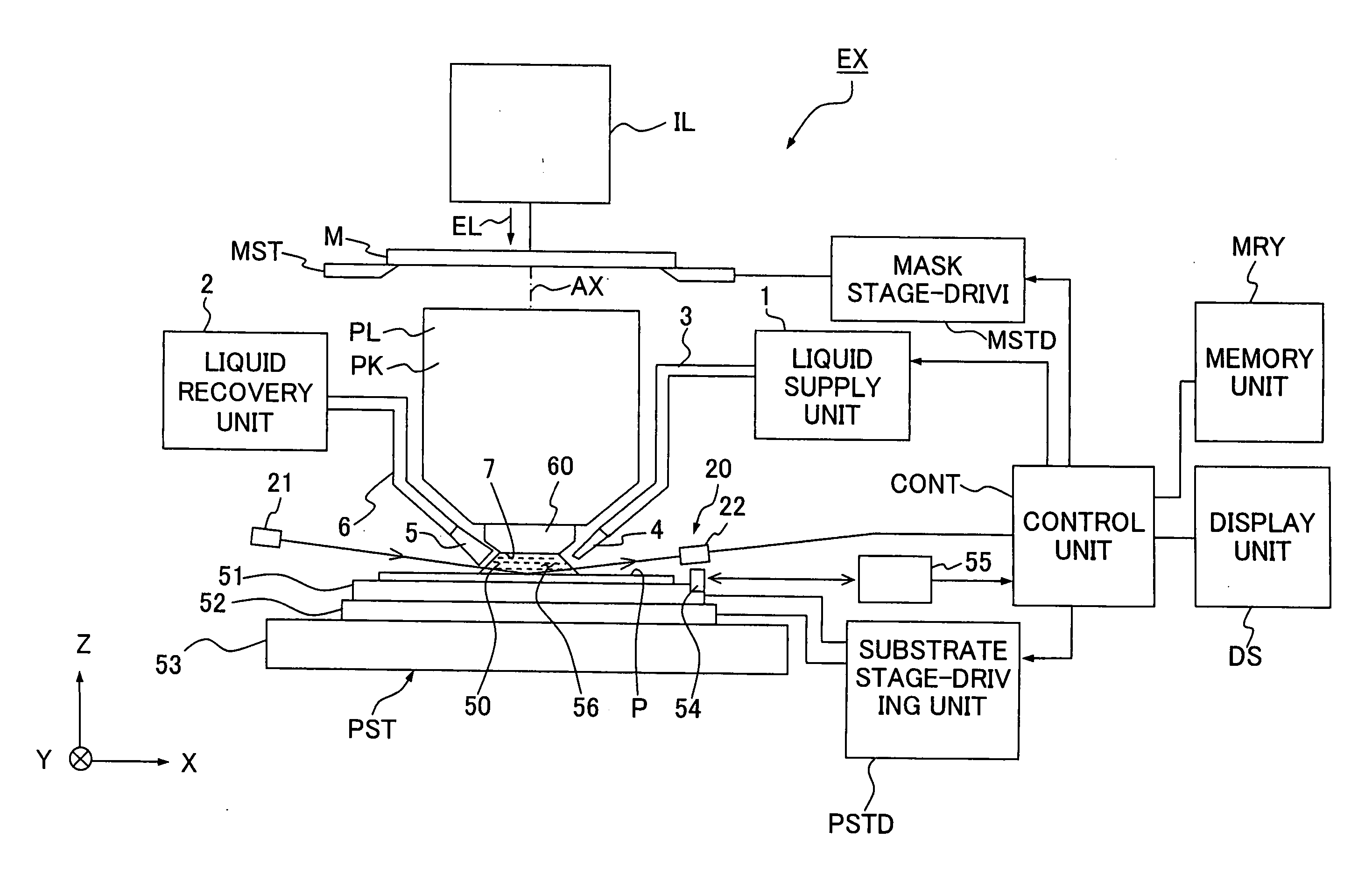
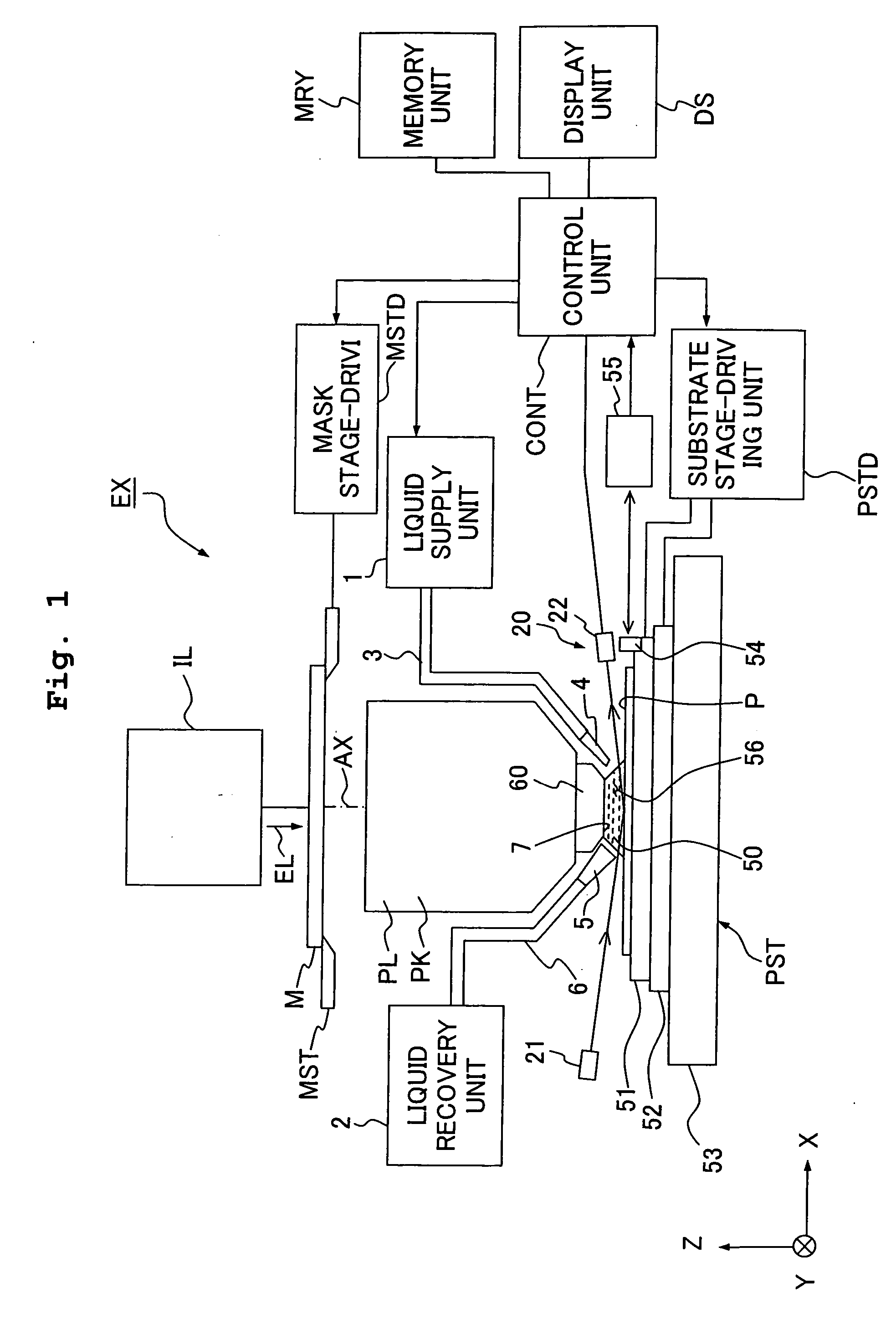
[0046] An explanation will be made below about the exposure apparatus and the method for producing the device according to the present invention with reference to the drawings. However, the present invention is not limited thereto. FIG. 1 shows a schematic arrangement illustrating an embodiment of the exposure apparatus of the present invention.

[0047] With reference to FIG. 1, an exposure apparatus EX includes a mask stage MST which supports a mask M, a substrate stage PST which supports a substrate P, an illumination optical system IL which illuminates, with an exposure light beam EL, the mask M supported by the mask stage MST, a projection optical system PL which performs projection exposure for the substrate P supported by the substrate stage PST with an image of a pattern of the mask M illuminated with the exposure light beam EL, a control unit CONT which collectively controls the overall operation of the exposure apparatus EX, a memory unit MRY which is connected to the contro...


PUM

PropertyMeasurementUnit
refractive indexaaaaaaaaaa
wavelengthaaaaaaaaaa

Abstract

An exposure apparatus performs an exposure of a substrate by filling at least a portion of the space between a projection optical system and the substrate with a liquid and projecting an image of a pattern onto the substrate via the projection optical system and the liquid. The apparatus includes a bubble detector that detects air bubble or bubbles in the liquid between the projection optical system and the substrate. Consequently, the exposure apparatus is capable of suppressing deterioration of a pattern image caused by bubbles in the liquid when an exposure is carried out while filling the space between the projection optical system and the substrate with the liquid.

Description

BACKGROUND OF THE INVENTION [0001] 1. Cross-Reference [0002] This application is a Divisional Application of U.S. patent application Ser. No. 11 / 147,288 filed Jun. 8, 2005, which in turn is a Continuation of International Application No. PCT / JP03 / 015737 filed Dec. 9, 2003 and which claims the conventional priority of Japanese patent Application Nos. 2002-357960 filed on Dec. 10, 2002 and 2003-393858 filed on Nov. 25, 2003. The disclosures of these prior applications are incorporated herein by reference in their entireties. [0003] 2. Field of the Invention [0004] The present invention relates to an exposure apparatus for exposing a substrate with a pattern image projected by a projection optical system in a state in which at least a part of a space between the projection optical system and the substrate is filled with a liquid. The present invention also relates to a method for producing a device based on the use of the exposure apparatus. [0005] 3. Description of the Related Art [00...

Claims


Application Information

Patent Timeline
Patent Type & Authority Applications(United States)
IPC IPC(8): G03B27/42G01N21/53G01N21/85G03F7/20H01L21/027
CPCG03F7/70341G03F7/2041
Inventor MIZUTANI, HIDEOMAGOME, NOBUTAKA
Owner NIKON CORP
Why Eureka
Try Eureka