Monitoring and control of mammographic computer-aided detection processing

Inactive Publication Date: 2006-06-15
R2 TECHNOLOGY INC
View PDF11 Cites 15 Cited by
  • Summary
  • Abstract
  • Description
  • Claims
  • Application Information

AI Technical Summary

Benefits of technology

[0010] Preferably, each film case icon occupies an area of said display sufficient to graphically communicate the current state at a viewing distance of at least five (5) meters. Thus, for example, the graphical status indicator allows the technologist to effectively monitor the scanning process with occasional glances from across the clinic floor, or occasional glances through a doorway, without needing to be physically adjacent to the display device. In another preferred embodiment, the display comprises a touchscreen and the film case icons have softbutton functionality allowing fast, one-touch access to the details of any particular film case by touching its film case icon. Each of the film case icons graphically communicates the current state of its corresponding film case by varying at least one of a color, size, visual texture, or shape configuration according to that current state.
[0011] According to another preferred embodiment, seamless orchestration of (i) film mammogram scanning, CAD processing, and dispensing, and (ii) digital mammogram receiving, CAD processing, and dispensing, is facilitated. A plurality of film cases is scanned to generate digitized versions thereof, each film case comprising at l

Problems solved by technology

Workflow processes associated with mammography, including CAD-related workflow processes, implicate substantial cost issues in practical clinical environments.
Because film-based mammograms require digitization prior to performance of CAD algorithms, a substantial number of workflow-related issues can arise.
Several workflow issues relating to film-based mammography CAD relate to the slowness of the digitization or scanning process.
However, although progress has been made toward automation of the film scanning process, as reflected in WO 02/43457 A2, which is incorporated by reference herein, and which describes automatic film orientatio

Method used


Image

  • Monitoring and control of mammographic computer-aided detection processing
  • Monitoring and control of mammographic computer-aided detection processing
  • Monitoring and control of mammographic computer-aided detection processing

Examples


Embodiment Construction

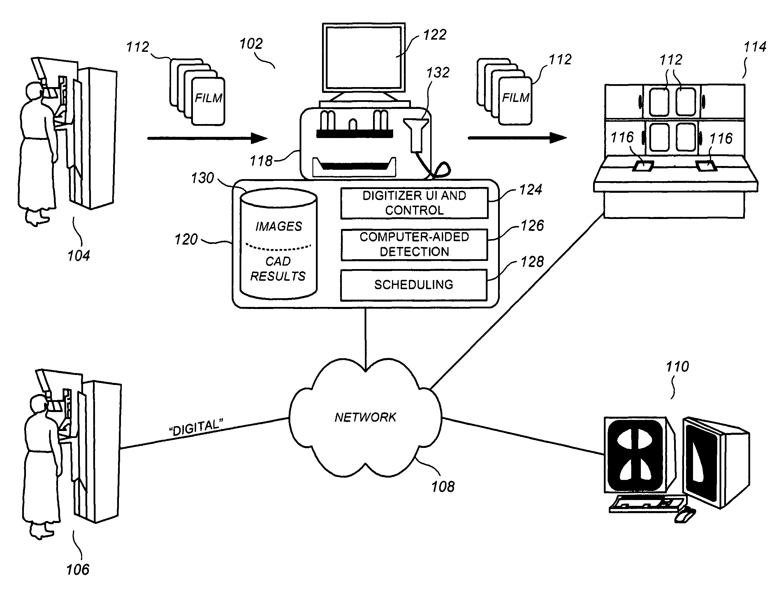
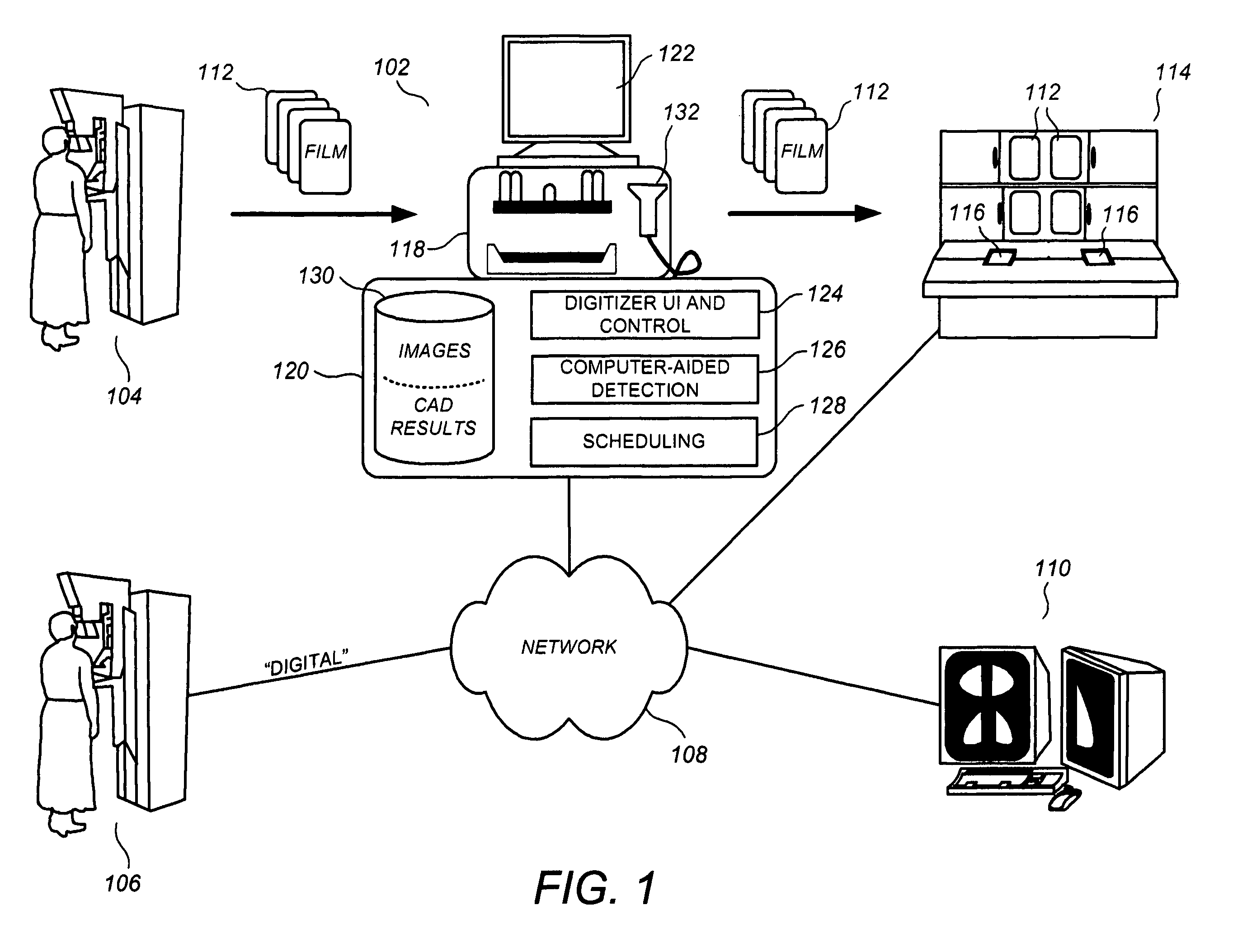
[0021]FIG. 1 illustrates a CAD station 102 in a combination film-based and digital mammography environment according to a preferred embodiment, including a film-screen mammogram acquisition device 104 and a digital mammogram acquisition device 106. The digital mammogram acquisition device 106 is coupled to a network 108, usually a HIS / RIS (Hospital Information System / Radiology Information System) network. As used herein, digital case refers to a group of mammogram images corresponding to a patient and acquired from a digital mammogram acquisition device. Although a symptomatic persons undergoing the mammographic imaging process are termed “clients” rather than “patients” in many clinics to denote that they are not symptomatic, the single term “patient” is used herein for simplicity and clarity of description. The group of digitally-acquired mammogram images forming the digital case is usually obtained during the same patient visit. The network 108 transfers the digital cases to the ...


PUM


Abstract

A system, method, and related computer program products for processing mammographic data are described. A digitizer receives a plurality of film cases arranged in a film case sequence, each film case comprising at least one mammographic film, the digitizer scanning each film case for generating a digitized version thereof. A processor processes the digitized versions according to at least one computer-aided detection (CAD) algorithm for detecting anatomical abnormalities therein. A display coupled to the processor displays a graphical status indicator comprising a plurality of film case icons, each film case icon corresponding to one of the film cases, wherein the film case icons are spatially ordered according to the film case sequence, and wherein each film case icon is configured to graphically communicate a current state of the scanning/processing for its corresponding film case.

Description

FIELD [0001] This patent specification relates to computer-aided detection (CAD) workflow processes in medical imaging environments. More particularly, this patent specification relates to monitoring and controlling the CAD processing of film-based and / or digitally-acquired mammogram images. BACKGROUND [0002] Computer-aided detection (CAD) generally refers to the use of computers to analyze medical images to detect anatomical abnormalities therein. Sometimes used interchangeably with the term computer-aided detection are the terms computer-aided diagnosis, computer-assisted diagnosis, or computer-assisted detection. CAD results are mainly used by radiologists and other medical professionals as “secondary reads” or secondary diagnoses tools. When analyzing a medical image, the radiologist usually makes his or her own analytical determinations before looking at the CAD results, which either verify those determinations or trigger further inspection of the image. Some CAD implementation...

Claims


Application Information

Patent Timeline
IPC IPC(8): G06K9/00
CPCG06T7/0012G06T2200/24G06T2207/10016G06T2207/30068
Inventor MARSHALL, JULIANIVEY, MARK B.MATUSKA, BRIAN T.JOHNS, JOHN R. II
Owner R2 TECHNOLOGY INC
Why Eureka
Try Eureka