Machining fixture for centering and holding workpiece

a technology of workpiece centering and workpiece holding, which is applied in the direction of chucks, manufacturing tools, mechanical equipment, etc., can solve the problems of high cost, time-consuming and labor-intensive, and particularly difficult to machining large-diameter workpieces such as turbine rotors, on vertical turret lathes

Active Publication Date: 2006-06-22
GENERAL ELECTRIC CO
View PDF28 Cites 13 Cited by
  • Summary
  • Abstract
  • Description
  • Claims
  • Application Information

AI Technical Summary

Benefits of technology

[0007] One more particular exemplary embodiment of the centering and holding fixture further includes an upper annular sleeve wall extending upwardly from the top of the annular sleeve. An extension head attached to the extension shaft radially overlaps the upper annular sleeve wall and has a downwardly tapering radially outer conical edge. The radia

Problems solved by technology

This is particularly difficult for machining large diameter workpieces, such as turbine rotors

Method used


Image

  • Machining fixture for centering and holding workpiece
  • Machining fixture for centering and holding workpiece
  • Machining fixture for centering and holding workpiece

Examples


Embodiment Construction

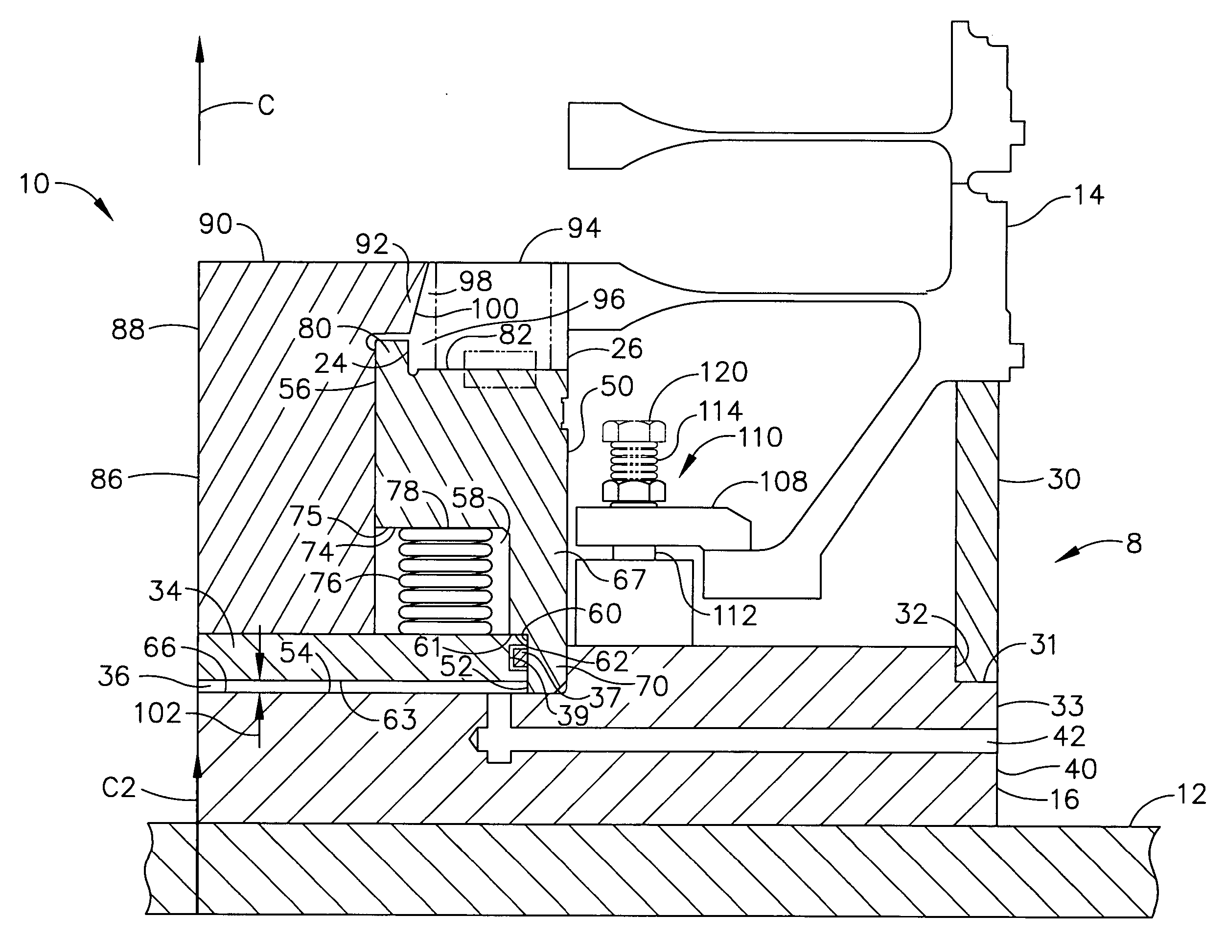
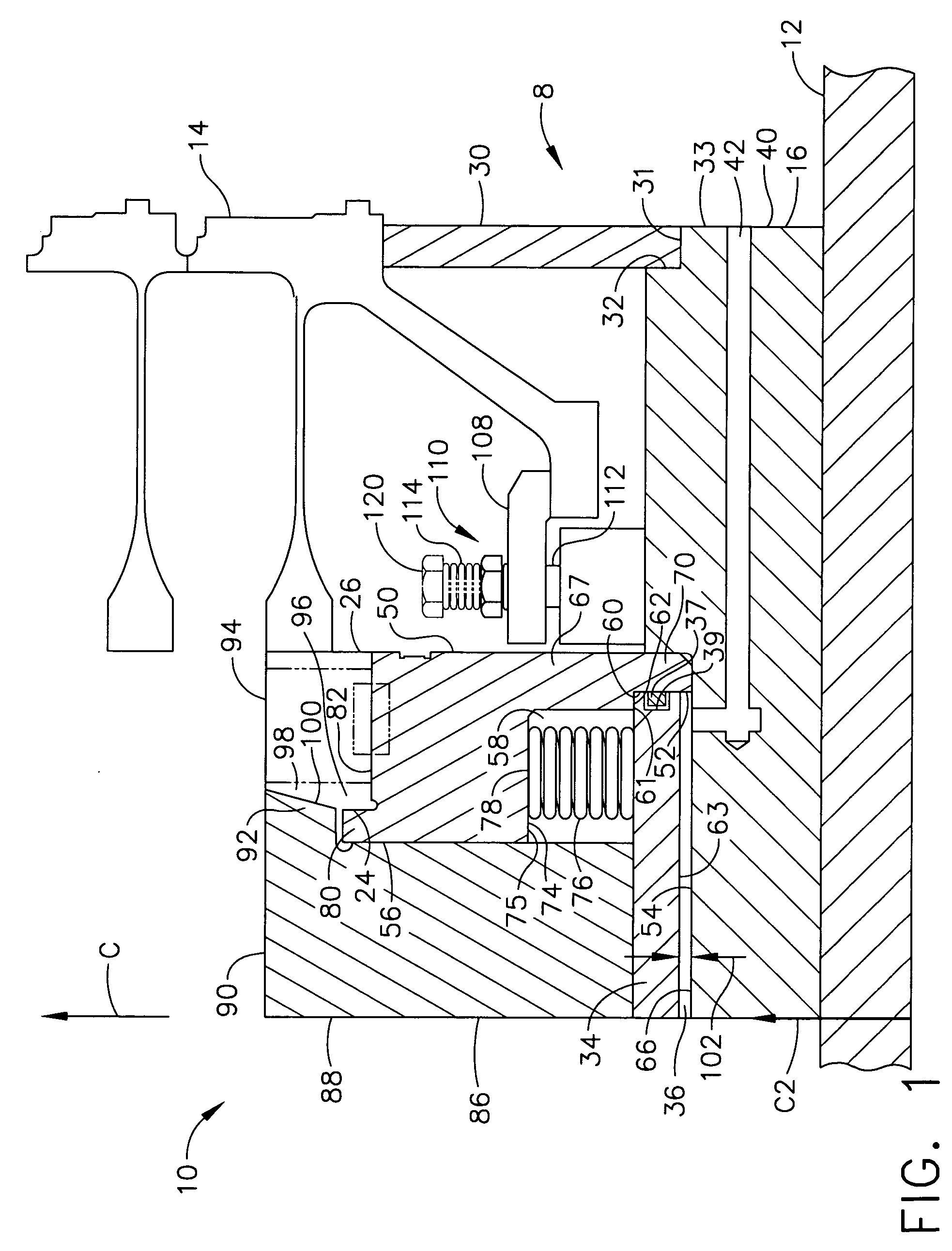
[0011] Illustrated in FIG. 1 is a fixtured machining assembly 8 including an annular workpiece 14 mounted in a centering and holding fixture 10 fixedly attached to a horizontal rotary table 12 designed for rotation about a vertical axis C2 of a machine tool such as a vertical lathe (not illustrated). The fixture 10 is designed to releasably center and carry an annular workpiece 14 having a center axis C. The fixture 10 is designed for aligning the center axis C of the workpiece 14 with the vertical axis C2 of the rotary table 12. The fixture 10 includes a cylindrical base 16 relatively fixedly mounted to the rotary table 12.

[0012] The fixture 10 includes a radially outer support ring 30 which vertically supports the annular workpiece 14 and rests within a radially outer groove 31 illustrated herein as an outer annular rabbet 32 along a radially outer edge 33 in the base 16. An exemplary cylindrical piston 34 is disposed within an exemplary cylindrical piston chamber 36. A pressuriz...


PUM

PropertyMeasurementUnit
Flexibilityaaaaaaaaaa
Stress optical coefficientaaaaaaaaaa

Abstract

A centering and holding fixture includes a base, a piston disposed within a piston chamber at least partially located within the base, and a radially flexible ring connected to the piston by force transmission apparatus operable to contract and expand the radially flexible ring by upward and downward motions respectively of the piston. The flexible ring may be slotted and may include alternating inwardly and outwardly extending radial slots extending axially through the flexible ring and extending radially inwardly and radially outwardly from radially outer and inner surfaces of the flexible ring respectively to axial stress relief holes extending axially through the flexible ring. The apparatus may further be operable to contract the radially flexible ring when the piston chamber is pressurized and to expand it when the piston chamber is depressurized. Spring loaded clamps mounted to the base may be used to secure a workpiece to the holding fixture.

Description

FIELD OF THE INVENTION [0001] This invention relates generally to multi axis machine tools such as vertical turret lathes (VTL's) with rotary tables and, more particularly, to fixtures and chucks used to position and hold workpieces on the rotary table. BACKGROUND OF THE INVENTION [0002] In most machining operations involving turning a workpiece, it is necessary to securely fix the workpiece in place upon a rotary table or other rotary work surface. Examples of such surfaces to which workpieces are secured include rotary tables, mill tables, fixtures or face plates and lathes, etc. Usually, the workpiece must be secured upon the surface to expose a selected portion of the workpiece upon which work such as cutting or machining is to be performed. In addition to securely fixing the workpiece in place, it is often necessary or desirable to provide fine adjustment in the position and alignment of the workpiece. For example, when a workpiece is secured to a rotary table, accurate alignme...

Claims


Application Information

Patent Timeline
IPC IPC(8): B23B31/12
CPCB23B31/4006B23B31/4073B23B2260/042B23B2260/136B23B2265/08B23B2270/025Y10T279/17521Y10T279/29Y10T82/2593Y10T279/1291Y10T279/1249Y10T279/1266Y10T279/17316B23B2270/027
Inventor CARRIER, CHARLES WILLIAM
Owner GENERAL ELECTRIC CO
Why Eureka
Try Eureka