Method and display element with reduced thermal stress

a display element and thermal stress technology, applied in the direction of discharge tube luminescnet screen, discharge tube/lamp details, organic semiconductor device, etc., can solve the problems of changing the thickness of the crystal layer, affecting the natural flexibility of the plastic substrate, and affecting the display effect, so as to avoid stress-induced damage and failure of the display

Inactive Publication Date: 2006-06-22
EASTMAN KODAK CO
View PDF7 Cites 31 Cited by
  • Summary
  • Abstract
  • Description
  • Claims
  • Application Information

AI Technical Summary

Benefits of technology

[0015] The invention provides a display device, and more particularly a flexible display device for which the stress in at least one layer of the light-emitting module in the display is substantially zero at the operating temperature. The layer can be chosen to be the most vulnerable layer in the light-emitting module to avoid stress-induced damage and failure of the display.

Problems solved by technology

On the other hands, under bending moments, the rigid display tends to lose its image over a large area, due to the fact that the gap between the substrates changes, thereby causing the liquid crystal material to flow away from the bending area, resulting in a changed crystal layer thickness.
Consequently, displays utilizing glass substrates are less suitable, when a more flexible or even bendable display is desired.
However, the natural flexibility of the plastic substrates presents problems, when trying to manufacture liquid crystal displays in a traditional manner.
The flexibility of the display is limited by the bending limitation of the display enclosures.
However, the introduction of grooves to the substrate causes significant stress concentration in the grooves.
This may lead to substrate fracture during manufacturing or usage.
When these structures carry an electrical current, joule heating takes place, and there is a potential for deleterious structural stress due to the mismatch of thermal expansion coefficients from one layer to the next.
The prior art has attempted to address the aforementioned drawbacks and disadvantages, but has achieved mixed results.
This method is generally less than ideal, since it adds unnecessary thickness to a device that is required to be sufficiently thin.
Additionally, such thickness restrictions hinder the possibility of employing additional layers that may be needed to minimize thermal stress.
This method has a distinct disadvantage in that it does not provide flexibility in adjusting the coefficient of thermal expansion and the thickness of the respective layers.

Method used


Image

  • Method and display element with reduced thermal stress
  • Method and display element with reduced thermal stress
  • Method and display element with reduced thermal stress

Examples


Embodiment Construction

[0025] This invention relates in general to a display device, and more particularly to a flexible display device comprising display component layers and display substrate and superstrate with properly selected properties (modulus, coefficient of thermal and moisture expansion, as well as thermal shrinkage behavior), dimensions and initial curvatures. When such a flexible display reaches its designed steady state operating temperature, the stress in the layer most subject to damage by stress in the display is minimized.

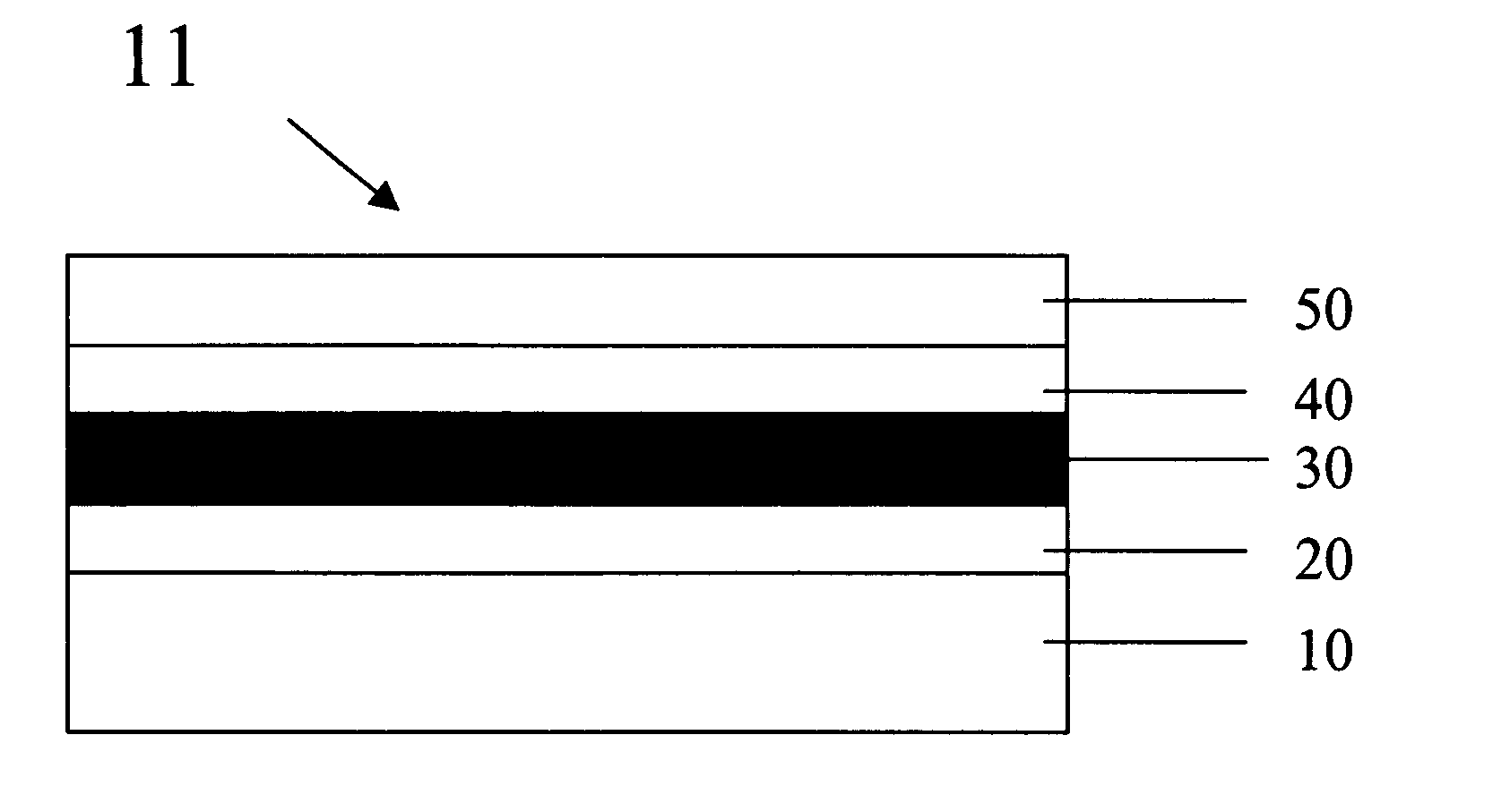
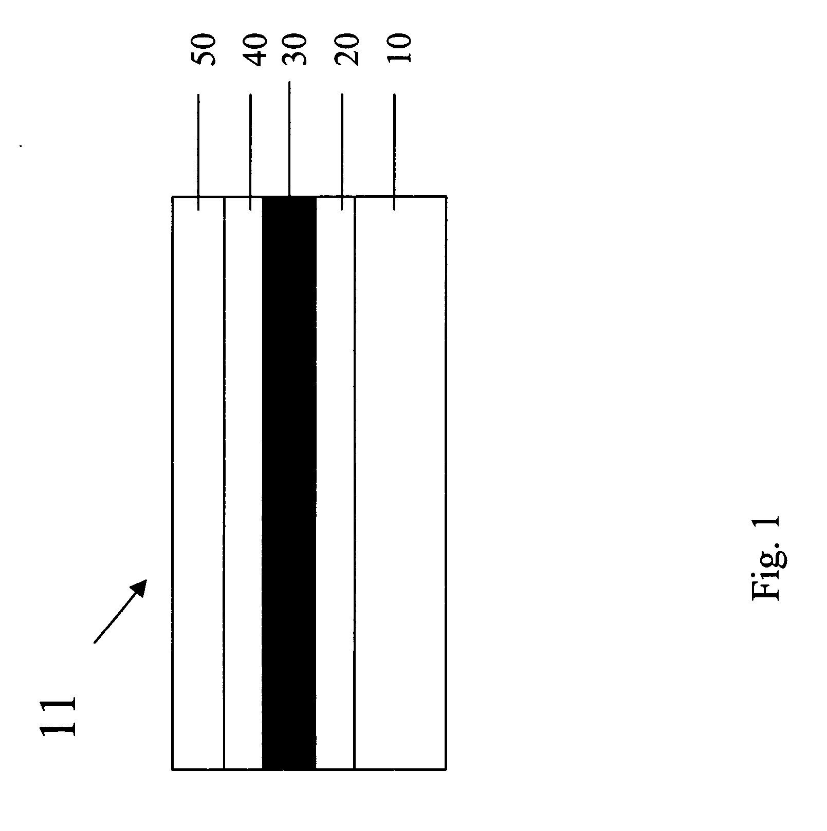
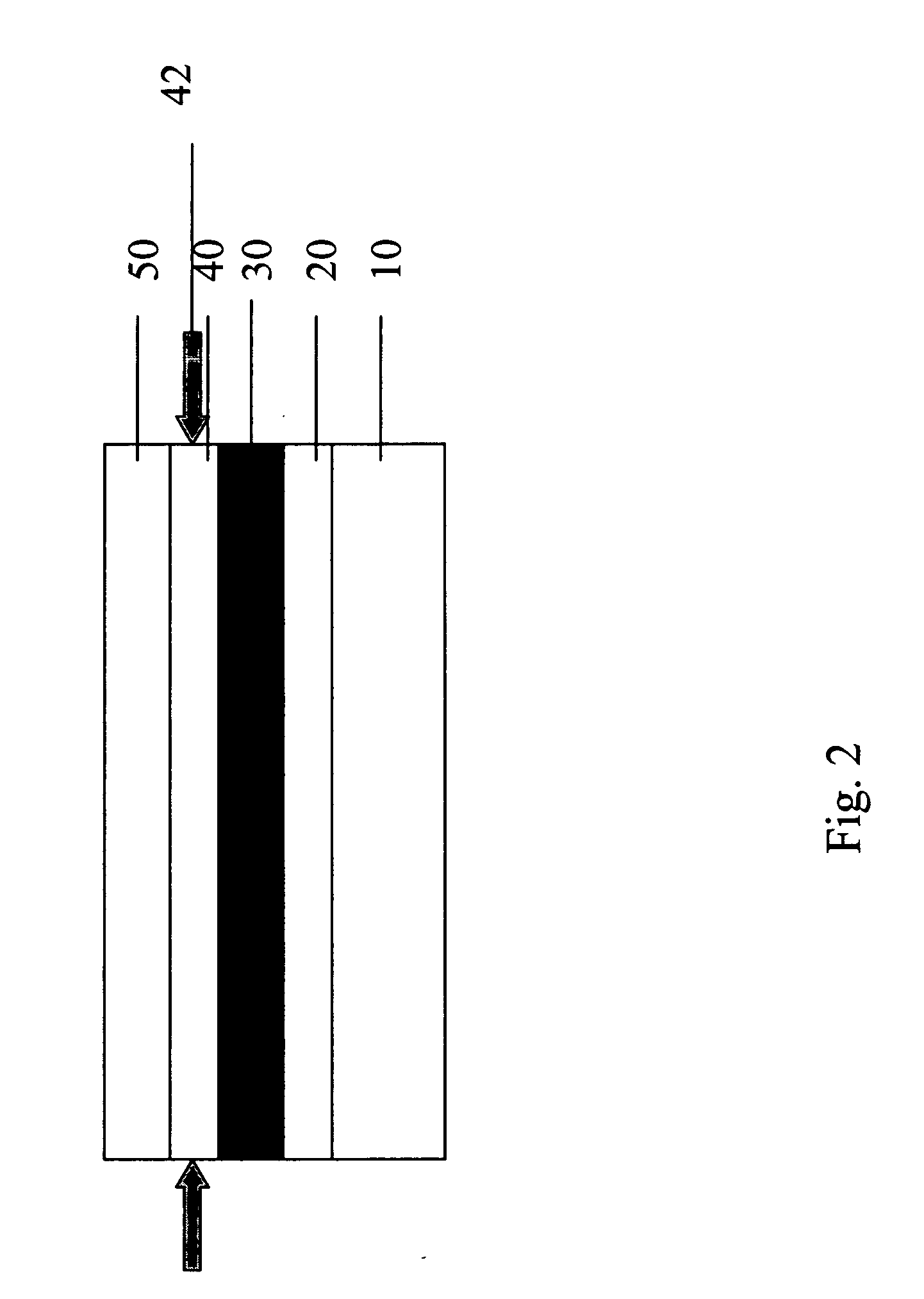
[0026] These and other objects of the invention are accomplished by providing a flexible display comprising in order a substrate layer, a conductive layer, a flexible light-emitting layer, a conductive layer, and a superstrate layer wherein the display is balanced such that the layer most subject to damage by stress is substantially stress-free. Furthermore, the substrate or superstrate may have a predetermined curvature in such a way that when the device reaches a st...


PUM


Abstract

The invention relates to a flexible display device comprising properly selected layers so that the thermal stress in the display can be reduced to avoid failure. The flexible display comprises in order a substrate layer, a conductive layer, a flexible light-emitting layer, a conductive layer, and a superstrate layer wherein the display is balanced such that the layer most subject to damage by stress is substantially stress-free. In addition, the invention provides methods of constructing such a balanced flexible display.

Description

FIELD OF THE INVENTION [0001] This invention relates in general to a display device, and more particularly to a flexible OLED display device comprising properly selected layers so that the thermal stress in the display can be reduced to avoid stress-induced damage or failure. BACKGROUND OF THE INVENTION [0002] Most of commercial displays devices, for example, liquid crystal displays (LCD), or solid-state organic light-emitting diode (OLED) are rigid. LCD comprise two plane substrates, commonly fabricated by a rigid glass material, and a layer of a liquid crystal material or other imaging layer, and arranged in-between said substrates. The glass substrates are separated from each other by equally sized spacers being positioned between the substrates, thereby creating a more or less uniform gap between the substrates. Further, electrode means for creating an electric field over the liquid crystal material are provided and the substrate assembly is then placed between crossed polarizer...

Claims


Application Information

Patent Timeline
Patent Type & Authority Applications(United States)
IPC IPC(8): H01J1/62H01J63/04
CPCH01L51/0097H01L51/52H01L51/5237H01L2251/5338Y02E10/549H10K77/111H10K50/80H10K50/841H10K2102/311
Inventor GAO, ZHANJUN
Owner EASTMAN KODAK CO
Why Eureka
Try Eureka