Display apparatus

a technology of display apparatus and display screen, which is applied in the field of display screen, can solve the problems of wasting power, affecting the operation, and affecting the picture quality of the display screen,

Inactive Publication Date: 2006-06-22
SAMSUNG ELECTRONICS CO LTD
View PDF5 Cites 16 Cited by
  • Summary
  • Abstract
  • Description
  • Claims
  • Application Information

AI Technical Summary

Benefits of technology

[0010] Accordingly, it is an aspect of the present invention to provide a display apparatus in which an image sticking phenomenon is decreased while the display apparatus continuously displays a still picture in response to a shutdown signal transmitted from a computer main body.

Problems solved by technology

However, such a conventional display apparatus supporting the DPVL communication system continuously displays the still picture when it receives the shutdown signal from the computer main body, such that any number of operation problems can arise.
For example, an image sticking (or afterimage) phenomenon can arise, thereby deteriorating picture quality of the display apparatus.
Further, even though there is no video data transmitted from the computer main body, the display apparatus continuously operates, thereby wastefully consuming power.
Also, in the case where the conventional display apparatus supporting the DPVL communication system continuously displays the still picture in response to the shutdown signal, it is difficult for a user to distinguish whether the display apparatus is displaying the still picture due to continuously receiving the same video data from the computer main body, or due to receiving the video data stored in the frame buffer without receiving the video data from the computer main body in response to the shutdown signal.

Method used


Image

  • Display apparatus
  • Display apparatus
  • Display apparatus

Examples


first embodiment

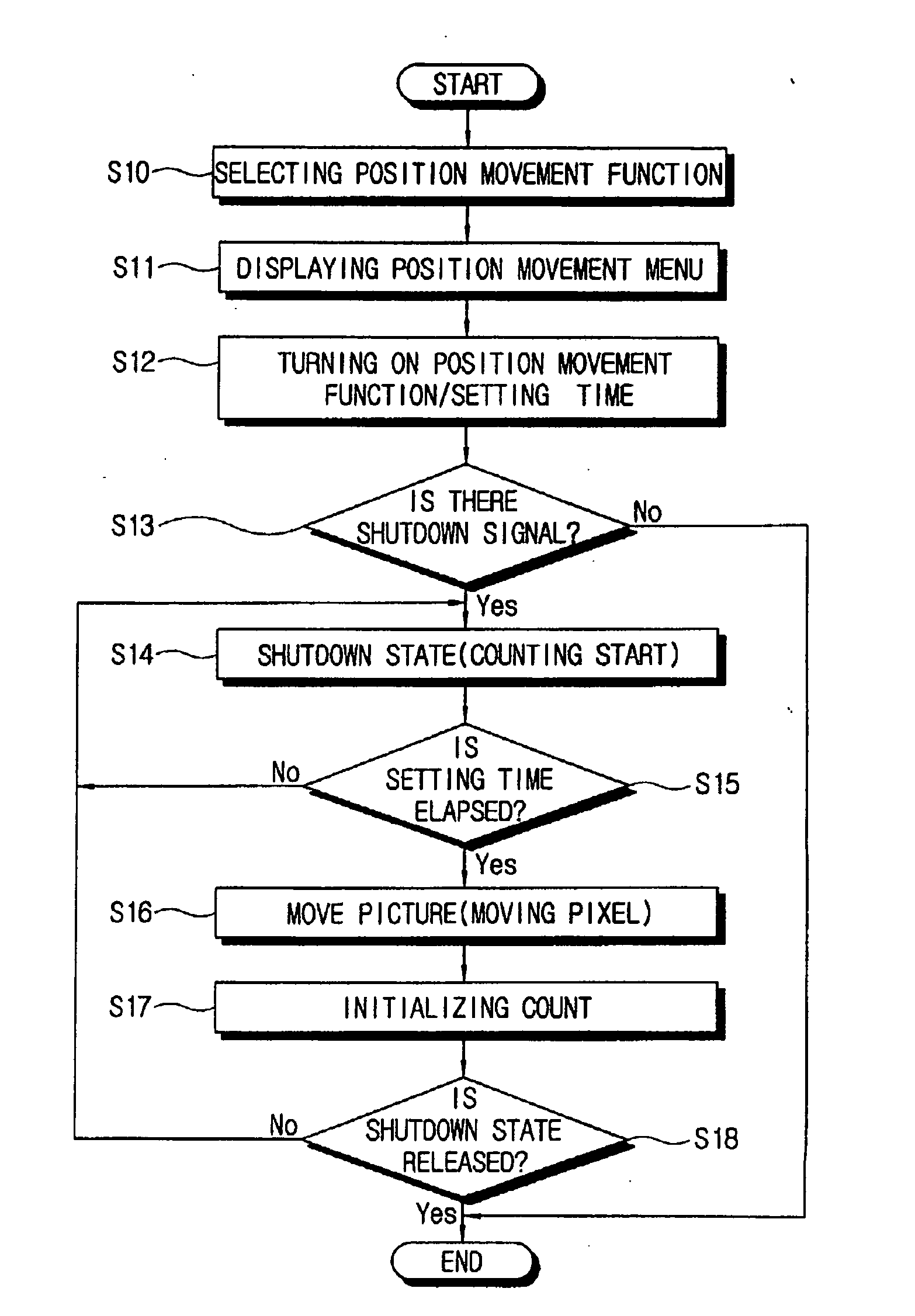
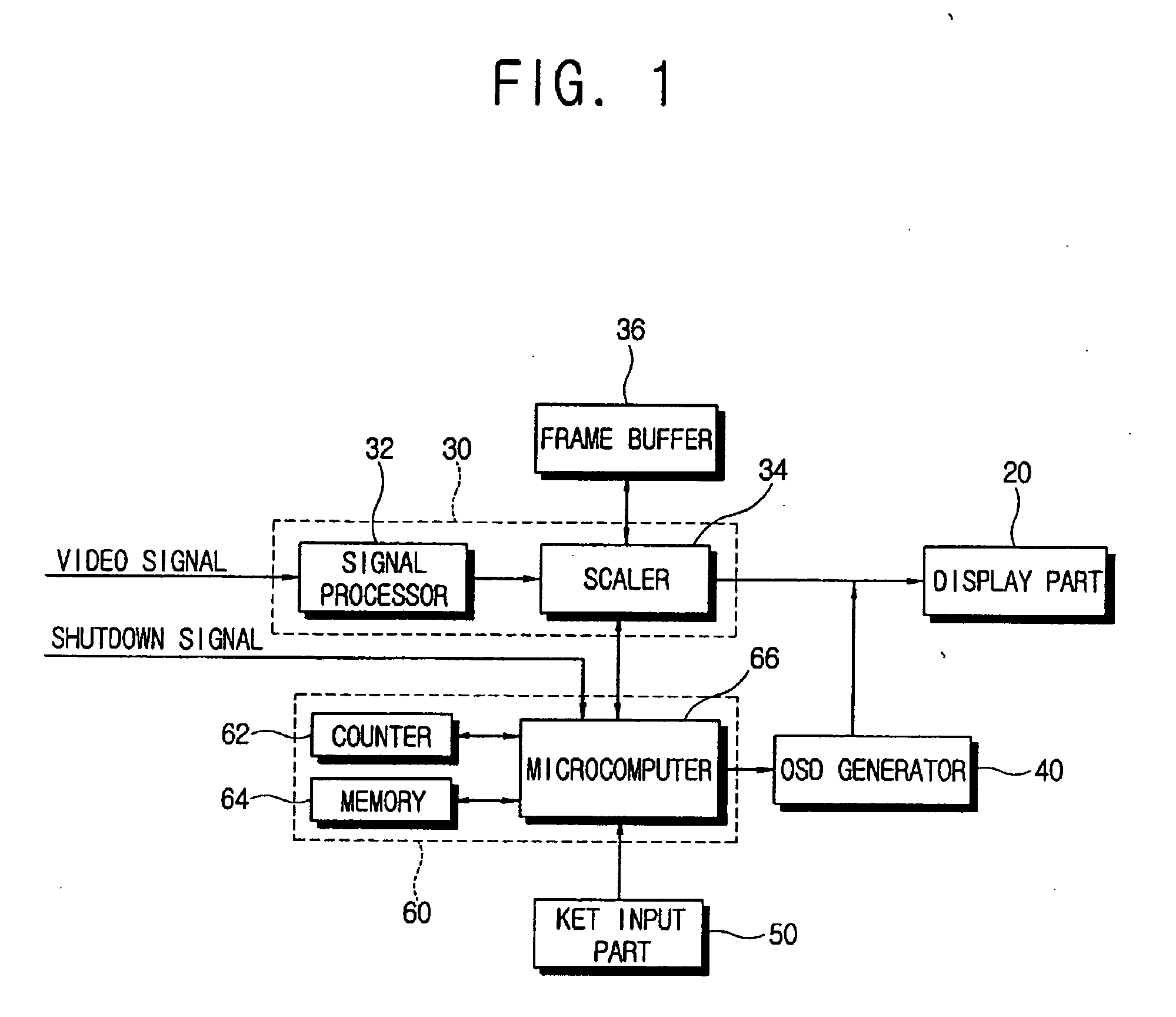
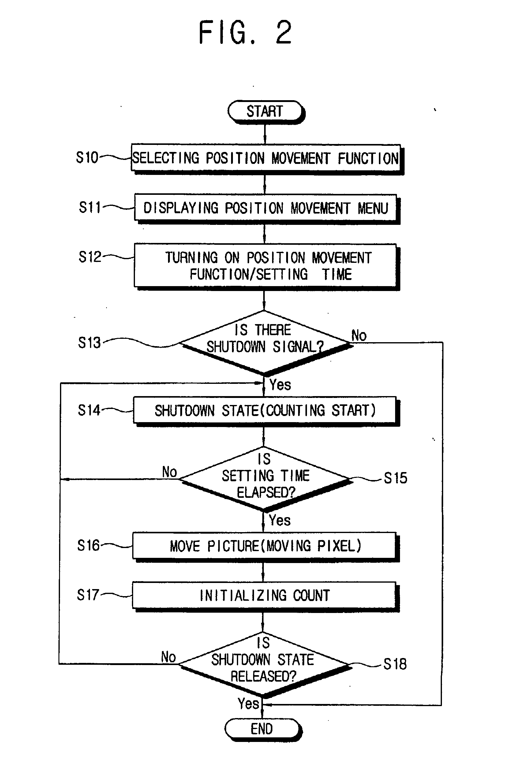
[0045] Hereinbelow, a control flowchart of the display apparatus according to the present invention will be described with reference to FIG. 2. At operation S10, a user selects the position movement function. Accordingly, at operation S11, the microcomputer 66 controls the OSD generator 40 to display the position movement menu. At operation S12, when a user sets the position movement function to the on state through the position movement menu and inputs the time, the microcomputer 66 controls the memory 64 to store the on setting value and the set time information.

[0046] At operation S13, the microcomputer 66 determines whether the shutdown signal is output from the computer main body. In the case wherein the shutdown signal is output from the computer main body, the display apparatus enters the shutdown state at operation S14, during which, the microcomputer 66 controls the scaler 34 to display a still picture based on the frame information stored in the frame buffer 36. At this ti...

second embodiment

[0058] Hereinbelow, a control flowchart of the display apparatus according to the present invention will be described with reference to FIG. 4. At operation S20, a user selects the power saving mode. Accordingly, at operation S21, the microcomputer 66′ controls the OSD generator 40′ to display the power saving function menu. At operation S22, when a user sets the power saving mode to the on state through the power saving function menu and inputs the time, the microcomputer 66′ controls the memory 64′ to store the on setting value and the set time information.

[0059] At operation S23, the microcomputer 66′ determines whether the shutdown signal is output from the computer main body. In the case wherein the shutdown signal is output from the computer main body, the display apparatus enters the shutdown state at operation S24, during which, the microcomputer 66′ controls the scaler 34′ to display a still picture based on the frame information stored in the frame buffer 36. At this time,...

third embodiment

[0069] Thus, the display apparatus according to the present invention displays the shutdown entering message when it receives the shutdown signal from the computer main body and enters the shutdown state, during which the still picture is displayed on the basis of the frame information stored in the frame buffer 36. Thereafter, when a user asks about the current state of the display apparatus, the display apparatus displays the shutdown message, thereby preventing a user from being confused about the operation being performed.

[0070] According to the third embodiment of the present invention, the display apparatus has a structure to prevent a user from being confused while the display apparatus receives the shutdown signal from the computer main body and is in the shutdown state. However, the display apparatus is not limited to the foregoing structure. Alternatively, in yet other embodiments of the present invention, the display apparatus may further comprise the power supply 70 like...


PUM


Abstract

A display apparatus for communicating with a computer main body through a DPVL system, wherein the display apparatus is provided with a video signal processor to process a video signal output from a computer main body into a displayable video signal, a frame buffer to store frame information corresponding to the video signal, and a controller to control the video signal processor to display a picture based on the frame information stored in the frame buffer when a predetermined shutdown signal is output from the computer main body, and change the picture on the basis of the stored frame information when a predetermined period has elapsed after receiving the shutdown signal. Thus, the present invention provides a display apparatus in which an image sticking phenomenon is decreased, wasteful power consumption is reduced, and which can prevent a user from being confused while the display apparatus continuously displays a still picture.

Description

CROSS-REFERENCE TO RELATED APPLICATIONS [0001] This application claims the benefit under 35 U.S.C. §119(a) of Korean Patent Application No. 10-2004-0108896, filed in the Korean Intellectual Property Office on Dec. 20, 2004, the entire disclosure of which is incorporated herein by reference. BACKGROUND OF THE INVENTION [0002] 1. Field of the Invention [0003] The present invention relates to a display apparatus for supporting a digital packet video link (DPVL) system. More particularly, the present invention relates to a display apparatus which can decrease an image sticking phenomenon arising in a shutdown state when displaying a still picture as a shutdown signal is transmitted from a computer main body to the display apparatus. The present invention can further reduce wasteful power consumption, and offer various messages to prevent a user from being confused as to the operation being performed. [0004] 2. Description of the Related Art [0005] In conventional computer systems, a dig...

Claims


Application Information

Patent Timeline
Patent Type & Authority Applications(United States)
IPC IPC(8): G09G5/08
CPCG09G3/007G09G5/006G09G2320/046G09G2330/021G09G2330/022G09G2360/18G06F3/14
Inventor KIM, YOUNG-CHAN
Owner SAMSUNG ELECTRONICS CO LTD
Why Eureka
Try Eureka