Driving Liquid Crystal Display with a Polarity Inversion Pattern

a liquid crystal display and matrix technology, applied in non-linear optics, static indicating devices, instruments, etc., can solve the problems of poor de-interlacement or de-interlacement of television applications of active matrix liquid crystal displays, and achieve the effect of reducing image sticking

Inactive Publication Date: 2008-11-20
KONINKLIJKE PHILIPS ELECTRONICS NV
View PDF6 Cites 6 Cited by
  • Summary
  • Abstract
  • Description
  • Claims
  • Application Information

AI Technical Summary

Benefits of technology

[0004]An object of the present invention is to provide driving a matrix of pixels with a polarity inversion pattern, which further reduces image sticking. The invention is defined by the independent claims. The dependent claims define advantageous embodiments.
[0006]By excluding the first set of pixels from being driven with the inverted polarity pattern, during the second frame, which means that this set of pixels is driven with the first polarity pattern during this second frame, the regular scheme of inverting the pattern for subsequent frames is interrupted for this first set of pixels. By continuing again inverting the polarity pattern during the third frame, effectively the regular scheme of inverting the pattern for subsequent frames is resumed again, however, now with an opposite polarity with respect to the odd and even frames. As a result, any non-zero DC-component built-up before the second frame due to stationary differences between the content of odd and even frames, is compensated from the second frame onwards because the polarity of the odd and even frames is reversed. Hence, even for television signals with poor or no de-interlacing image sticking is reduced.
[0009]If the first set of pixels and the mutually different sets of pixels each comprise less then half of the total amount of pixels in the matrix, a flicker effect caused by the change of the polarity scheme is reduced.
[0014]A particular feature of the present invention relates to a video signal manipulating circuit for compensating for biasing difference. This feature reduces the visibility of the change of the polarity pattern caused by the relatively slow response of especially Liquid Crystal Display pixels to drive signals.

Problems solved by technology

This problem is particularly encountered in no de-interlace or poor de-interlace television applications of active matrix liquid crystal displays.

Method used


Image

  • Driving Liquid Crystal Display with a Polarity Inversion Pattern
  • Driving Liquid Crystal Display with a Polarity Inversion Pattern
  • Driving Liquid Crystal Display with a Polarity Inversion Pattern

Examples


first embodiment

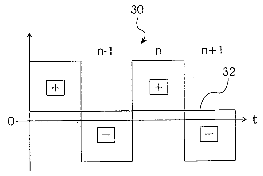
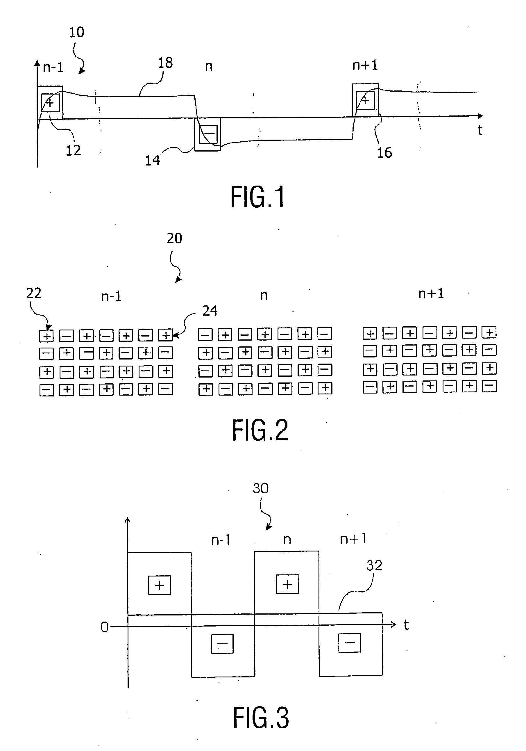
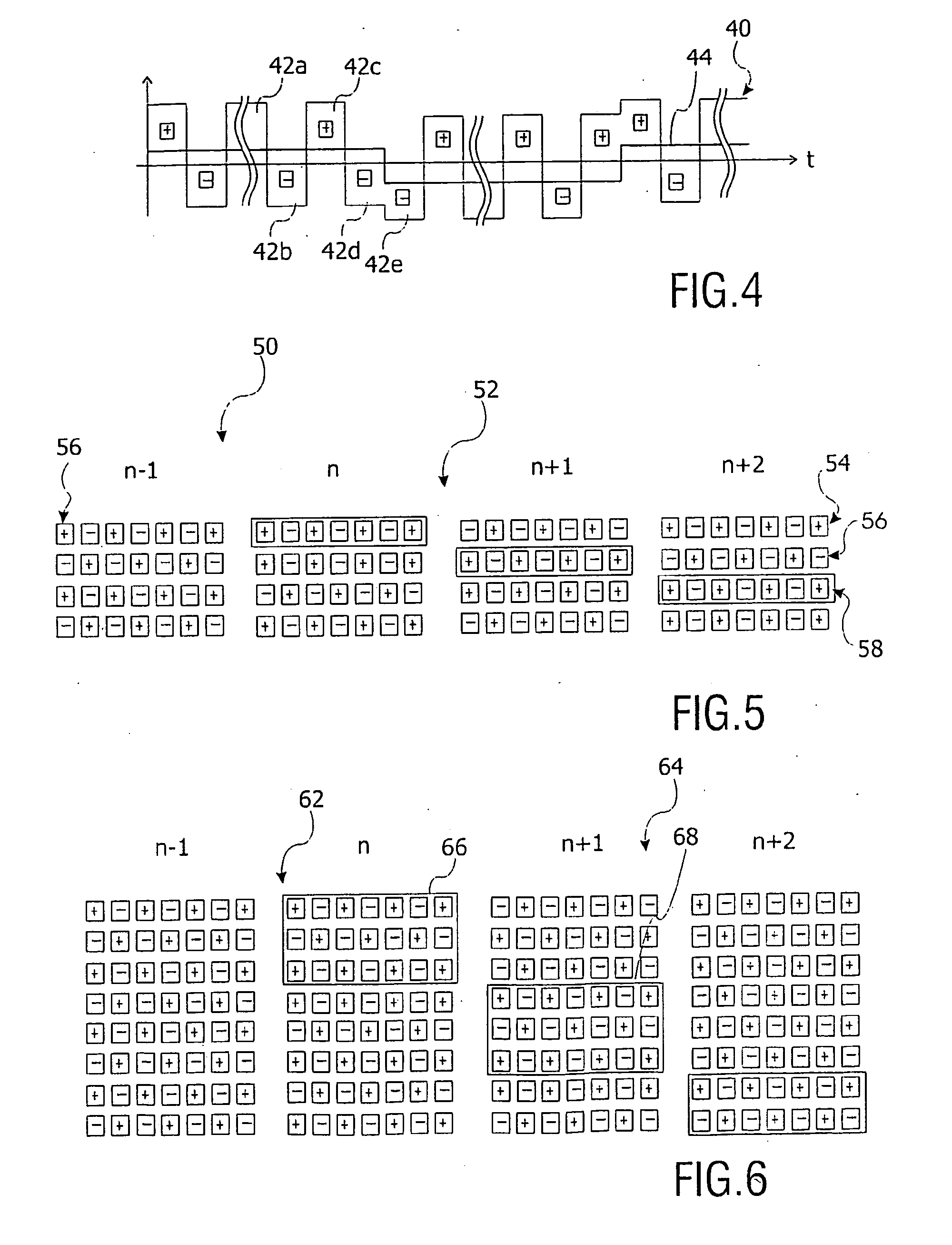
[0032]FIG. 4 shows a graph of a driving voltage 40 for a pixel as function of time t according to the present invention, which driving voltage 40 has an alternating polarity during a predefined number of frames, exemplified by reference numerals 42a through 42d. Thereafter, the driving voltage 40 has an inverted polarity inversion scheme and repeats the polarity of frame 42d in frame 42e. This introduces a shift or a polarity alternation of a DC offset 44, thereby compensating for charge building up across a pixel for an extended period of time, since the DC offset 44 averages zero over time. Consequently, the driving voltage 40 according to the present invention prevents image retention on a liquid crystal display.

[0033]FIG. 5 shows a polarity inversion scheme 50 according to the first embodiment of the present invention for a matrix of pixels 52. The polarity for each pixel in subsequent frames n−1, n, n+1 and n+2 is indicated with “+” and “−”. The polarity of the pixels in the ma...

second embodiment

[0034]FIG. 6 shows a polarity inversion scheme 62 according to the present invention wherein the polarity inversion scheme excluding rows subsequently in subsequent frames is performed on a plurality of rows 66, 68 of a matrix of pixels 64 for frames n−1, n, n+1, n+2. The number of rows maintaining the same polarity in two consecutive frames should be less than a half of a total number of rows of the matrix, otherwise the frequency of polarity inversion on a pixel in the matrix 64 is smaller than the half of the frame frequency, and this may lead to visible large area flicker.

third embodiment

[0035]FIG. 7 shows a polarity inversion scheme 70 according to the present invention, wherein the polarity inversion scheme excluding a row or a plurality of rows is not restricted to a number of rows, but may also be applied rather to a number of consecutive pixels 74, 76. The polarity inversion exception is in an alternative embodiment not even restricted to consecutive pixels. In fact, it is only important to make a driving voltage, shown in FIG. 4 as reference numeral 40, for each pixel in a matrix 72. However, having the polarity inversion exception restricted to consecutive pixels provides a cheaper hardware solution.

[0036]During a change of the polarity inversion scheme, so when excluding a row, a plurality of rows, or pixels as described with reference to above figures, the light output of a liquid crystal display slightly increases for a normally black display and decreases for a normally white display. This difference 80 in light output, which is shown in FIG. 8, is visibl...


PUM

PropertyMeasurementUnit
polarityaaaaaaaaaa
response timeaaaaaaaaaa
timeaaaaaaaaaa

Abstract

This invention relates to driving a liquid crystal display with a polarity inversion. The liquid crystal display panel (98) comprises a matrix of pixels (52, 62, 72), which is driven with a sequence of image frames. The method comprises driving the pixels during a first frame (n−1) with a first polarity pattern; driving the pixels with exception of a first set of pixels (54, 66, 74) during a second frame (n) with an inverted polarity pattern; and driving the first set of pixels (54, 66, 74) with the inverted polarity pattern during a third frame (n+1).

Description

FIELD OF INVENTION[0001]This invention relates to driving a matrix of pixels with a polarity inversion scheme. In particular, this invention relates to preventing image sticking or image retention on an active matrix liquid crystal display device.BACKGROUND OF INVENTION[0002]An active matrix device, such as described in U.S. Pat. No. 6,469,684, which hereby is incorporated in the present specification by reference, comprises an inversion circuitry coupled to drive signals, which inversion circuitry has at least one Cole sequence generator providing random, semi-random, or pseudo-random sequence patterns of the matrix. The Cole sequence generator provides a sequence of inversion patterns of pixel biasing over several frames. Over time each pixel is presented with a substantially equal number of positive and negative drive levels to prevent the generation of undesirable display artifacts that might occur under a direct current bias. The prior-art patent further discloses that when usi...

Claims


Application Information

Patent Timeline
Patent Type & Authority Applications(United States)
IPC IPC(8): G09G3/36G02F1/133
CPCG09G3/3614G09G2320/0204G09G2320/0257G09G3/36G02F1/133G09G3/20
Inventor VAN DALFSEN, AGE JOCHEMSEVO, ALEKSANDAR
Owner KONINKLIJKE PHILIPS ELECTRONICS NV
Why Eureka
Try Eureka