Driving method for reducing image sticking

a technology of driving method and image sticking, applied in the direction of instruments, computing, electric digital data processing, etc., can solve problems such as image sticking problems, and achieve the effect of reducing image sticking and reducing image sticking

Active Publication Date: 2012-08-09
OPTRONIC SCI LLC
View PDF3 Cites 6 Cited by
  • Summary
  • Abstract
  • Description
  • Claims
  • Application Information

AI Technical Summary

Benefits of technology

[0010]The present invention discloses a driving method for reducing image sticking associated with images of a liquid crystal display. The liquid crystal display comprises a plurality of data lines, a plurality of scan lines and a plurality of pixel areas. The driving method comprises during a first period of time, sequentially turning on the plurality of scan lines and inputting data of a first image to the plurality of pixel areas; during a second period of time, sequentially turning on the plurality of scan lines and inputting data of a second image to the plurality of pixel areas; and between the first period of time and the second period of time, generating and applying a first voltage according to voltage levels corresponding to the data of the first image.
[0011]The present invention further discloses a driving method for reducing image sticking associated with images of a liquid crystal display. The liquid crystal display comprises a plurality of data lines, a plurality of scan lines and a plurality of pixel areas. The driving method comprises during a first period of time, sequentially turning on the plurality of scan lines and inputting data of a first image to the plurality of pixel areas; during a second period of time, sequentially turning on the plurality of scan lines and inputting data of a second image to the plurality of pixel areas; and between the first period of time and the second period of time, generating and applying a first voltage according to voltage levels corresponding to data of the first image on a first set of the plurality of data lines.

Problems solved by technology

Nevertheless, the data voltages are slightly asymmetric AC waveforms unavoidably so that a net DC voltage is formed after displaying an image for a period of time.
These accumulated impurities P generate an inner electric field E in the liquid crystal layer L1, which shields off the following data voltage to apply on the liquid crystal molecules X. Consequently, the liquid crystal molecules X cannot rotate to the correct direction and the image sticking problem occurs.

Method used


Image

  • Driving method for reducing image sticking
  • Driving method for reducing image sticking
  • Driving method for reducing image sticking

Examples


Embodiment Construction

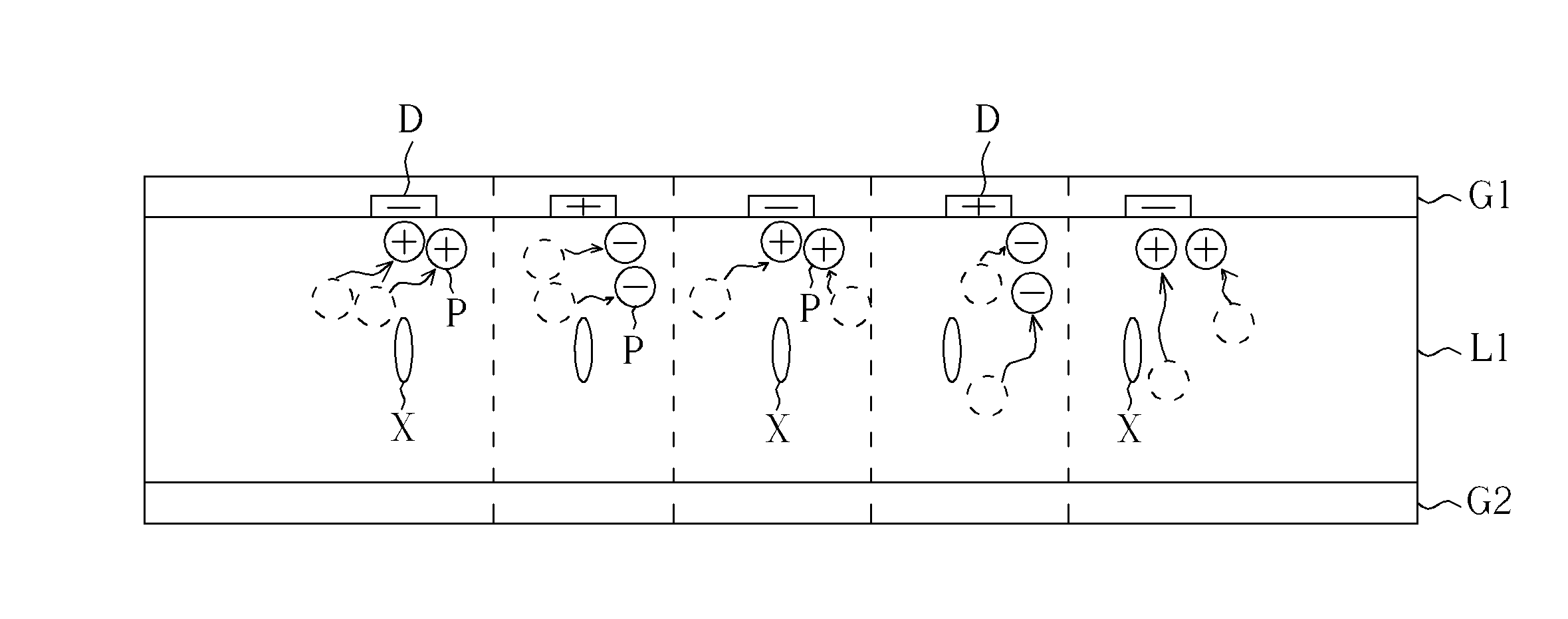
[0027]FIGS. 6 and 7 are diagrams illustrating the driving method to improve image sticking for an LCD to display images. As shown in FIG. 6, because a net DC electric field, which is induced by the imperfectly symmetric data voltages Vd, and the specific direction of the liquid crystal molecules X, which is determined by the voltage difference between the data voltage Vd and the common voltage Vcom, the impurities P move three-dimensionally to cross several data lines D in the liquid crystal layer L1. Finally the positive-polarized impurities P accumulate in a local region in the LC layer L1, and the negative-polarized impurities P accumulate in another local region in the LC layer L1. Please refer to FIG. 7, the present invention applies high voltages on the data lines D to avoid the impurity particles P pass through the data lines D as shown in FIG. 6. The high voltages applied on the data lines D trap the impurities P to prevent the impurities P from crossing several data lines D...


PUM


Abstract

A driving method with reducing image sticking effect is disclosed. The driving method includes applying a voltage on the data lines for trapping impurities crossing the data lines and lowering the degree of the image sticking effect, and applying different asymmetric waveforms to different data lines for trapping impurities crossing the data lines and lowering the degree of the image sticking effect.

Description

CROSS REFERENCE TO RELATED APPLICATIONS[0001]This is a continuation-in-part application of application Ser. No. 11 / 747,920, filed May 14, 2007.BACKGROUND OF THE INVENTION[0002]1. Field of the Invention[0003]The present invention relates to a driving method for reducing image sticking effect of display images, and more specifically, to a driving method for reducing image sticking effect of images on a liquid crystal display (LCD).[0004]2. Description of the Prior Art[0005]FIG. 1 is a diagram illustrating a cross-sectional view of a conventional liquid crystal display (LCD) 100. As shown in FIG. 1, the LCD 100 comprises two glass substrates, G1 and G2, and a liquid crystal (LC) layer L1 disposed between the glass substrates G1 and G2. A plurality of data lines (not shown) and a plurality of scan lines (not shown) are laid on the glass substrate G1 and are interwoven each other to form a plurality of the pixel areas. The liquid crystal layer L1 comprises liquid crystal molecules X, of ...

Claims


Application Information

Patent Timeline
Patent Type & Authority Applications(United States)
IPC IPC(8): G09G5/00G09G3/36
CPCG09G3/3611G09G3/3648G09G2320/0257G09G2310/06G09G2310/061G09G3/3655
Inventor LIU, PIN-MIAOLIEN, SHUI-CHIHHUANG, CHIA-HORNGLIAO, CHIEN-HUANGHO, YU-HSICHANG, TING-JUIHSIEH, YAO-JENSU, JENN-JIA
Owner OPTRONIC SCI LLC
Why Eureka
Try Eureka