Receiver with chopper stabilization and method thereof

a receiver and chopper technology, applied in the field of receivers, can solve problems such as distortions that can corrupt the message carried by the signal, unwanted noise to the signal,

Active Publication Date: 2006-06-22
GOOGLE TECH HLDG LLC
View PDF3 Cites 33 Cited by
  • Summary
  • Abstract
  • Description
  • Claims
  • Application Information

AI Technical Summary

Benefits of technology

[0008] In a third embodiment of the present invention, a method is provided for transforming a signal at a first operating frequency. The method includes the steps of down-converting the signal from the first operating frequency to a second operating frequency that is lower than the first operating frequency, low-pass filtering with chopper stabilization unwanted portions of the signal operating at the second operating frequency, and generating a final filtered signal at the second operating frequency.

Problems solved by technology

These techniques, however, inject unwanted noise to the signal, which in turn causes distortions that can corrupt the message carried by the signal.

Method used


Image

  • Receiver with chopper stabilization and method thereof
  • Receiver with chopper stabilization and method thereof
  • Receiver with chopper stabilization and method thereof

Examples


first embodiment

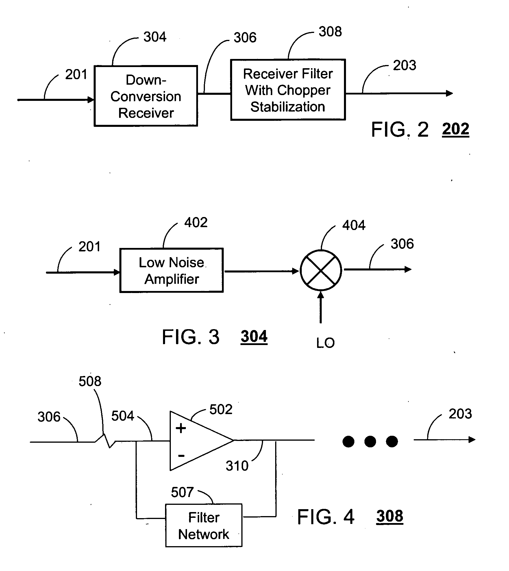
[0034]FIG. 5 depicts a block diagram of the OP AMP 502 in accordance with the present invention. In this embodiment, the OP AMP 502 comprises a reference oscillator 518, an up-conversion mixer 506, an amplifier 512 having at least one stage (depicted by the sequential dots), and a down-conversion mixer 516. For consistency with the above discussions, all elements 506, 512, 516 and 518 of the OP AMP 502 utilize differential signals.

[0035]FIG. 6 provides a spectral representation of the receiver filter 308 according to the embodiment of FIGS. 4 and 5. The spectral response at each node of the OP AMP 502 are illustrated sequentially by the letterings A through E and corresponding node signals 504, 510, 514, 310 and 203.

[0036] At the input of the OP AMP 502 (spectral image A), the differential signal 504 includes an ideal signal 602, which carries information relating to the message transmitted to the SCR 200. Adjacent to the ideal signal 602 are interferer signals 604. These signals m...

embodiment 540

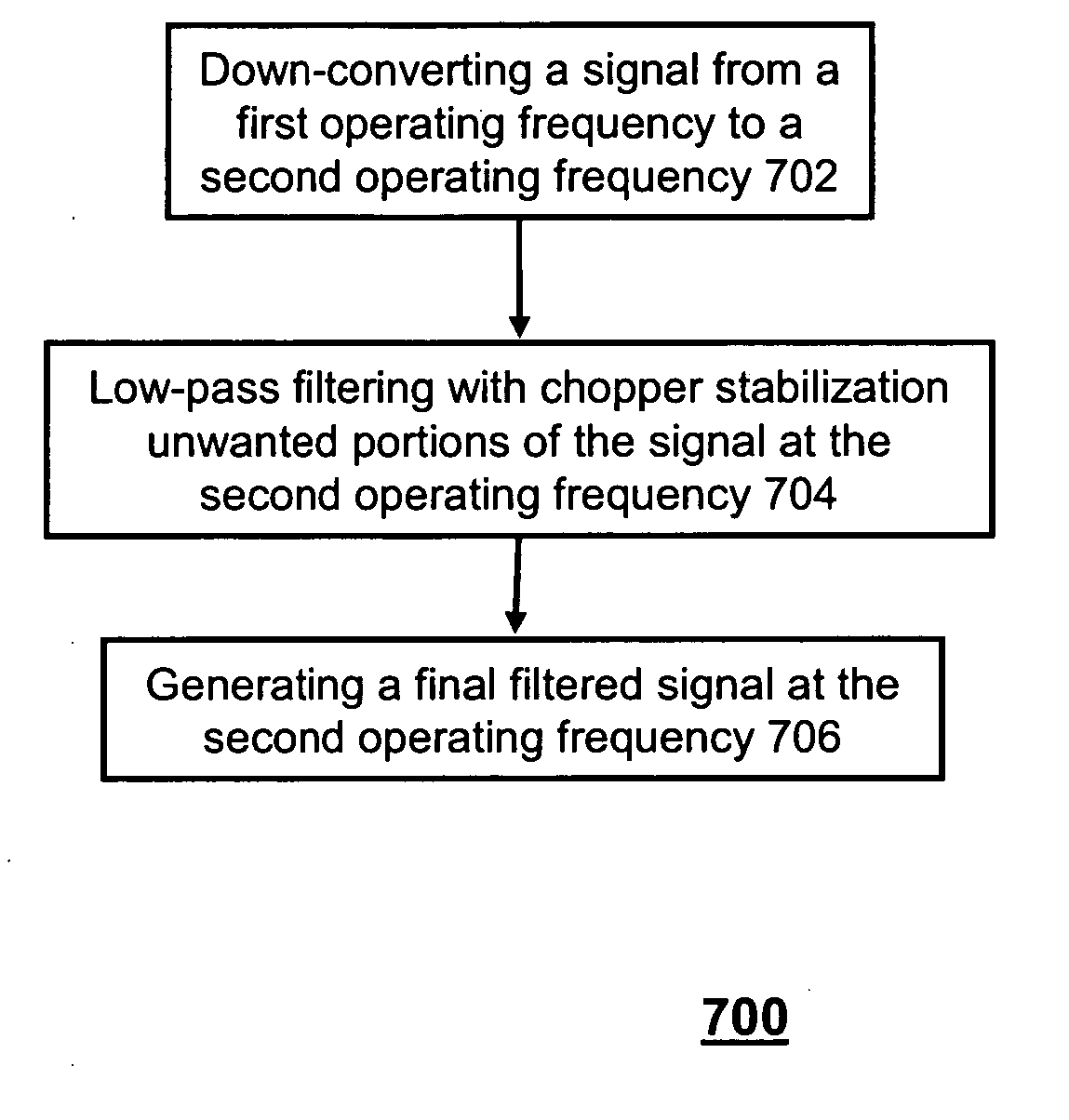
[0049]FIG. 9 illustrates supplemental embodiment of the receiver filter of FIG. 8 in accordance with the present invention. This embodiment adds a LPF 542 having at least one stage (as depicted by the sequential dots of FIG. 9) to the embodiment 540 of FIG. 8. Utilizing conventional LPF technology, the LPF 542 provides and nth order LPF to eliminate spectral noise that the bandpass filter amplifier 530 was unable to remove and generates the final filtered.

[0050]FIG. 10 is a spectral response of the embodiments of FIGS. 8 and 9 in accordance with the present invention. Spectral images A and B are the same as described in FIG. 6. Spectral image C illustrates the effect of the at least one bandpass filter amplifier 530 on signal 510. From a last stage of the bandpass filter amplifier 530 the signal 510 at the third operating frequency (fref) and its components are amplified as shown in spectral image C. Contemporaneously, the bandpass filter amplifier 530 removes unwanted portions of t...


PUM


Abstract

A receiver (202) has a down-conversion receiver (304) for transforming a signal (201) from a first operating frequency to a second operating frequency that is lower than the first operating frequency, and a receiver filter (308) with chopper stabilization for filtering unwanted portions of the signal (306) at the second operating frequency and for generating a final filtered signal (203) at the second operating frequency.

Description

FIELD OF THE INVENTION [0001] This invention relates generally to receivers, and more particularly to chopper stabilization and methods thereof in receivers. BACKGROUND OF THE INVENTION [0002] Wireless communications generally involve transmitting a signal with voice and / or data messages carried therein at a carrier frequency (e.g., 2 Giga Hertz) from one communication device to another. The receiving device in turn demodulates the signal to a baseband signal (nearly zero Hertz) for processing and presenting the voice and / or data message to a recipient of the receiving device. [0003] There are many demodulating techniques in the art. Among them are super heterodyne and direct conversion receivers. For each technique, the carrier frequency of the signal is translated to a baseband or nearly baseband signal. In the demodulation process, filtering and amplification techniques are used. These techniques, however, inject unwanted noise to the signal, which in turn causes distortions that...

Claims


Application Information

Patent Timeline
Patent Type & Authority Applications(United States)
IPC IPC(8): H04B1/10
CPCH03D7/161H03D7/18H04B1/10H04B1/28H03D1/00
Inventor BOLTON, JERRY T. JR.HECK, JOSEPH P.
Owner GOOGLE TECH HLDG LLC
Why Eureka
Try Eureka