Recycling method and manufacturing method for an image display apparatus

a technology of image display and recycling method, which is applied in the manufacture of electrode systems, cold cathode manufacturing, and electric discharge tubes/lamps, etc., can solve the problems of low brightness of display, and loss of image display apparatus functions, etc., to reduce luminance, reduce waste, and recycle with ease

Inactive Publication Date: 2006-06-22
CANON KK
View PDF20 Cites 1 Cited by
  • Summary
  • Abstract
  • Description
  • Claims
  • Application Information

AI Technical Summary

Benefits of technology

[0009] In view of the above problem, the present invention therefore has an object to make it possible to minimize disposal of waste parts and to recycle with ease a display whose luminance becomes low and whose life has ended. More specifically, the present invention aims at reconstructing a display by recycling processing through multiple steps without replacing (disposing) an electron emitter section that is a direct cause of reduction in luminance.

Problems solved by technology

There still remain problems in that the LCD exhibits a low brightness in images and a narrow view angle, and that the PDP exhibits a low contrast.
However, up to now, a display whose brightness becomes low and whose functions as an image display apparatus have been lost is not reused with the most part being disposed of.
The recycling of the display is possible in principle by only recycling or replacing degraded parts, but difficult in reality due to the structure, assembly process, cost, etc. of the display, and therefore has not been conducted.

Method used


Image

  • Recycling method and manufacturing method for an image display apparatus
  • Recycling method and manufacturing method for an image display apparatus
  • Recycling method and manufacturing method for an image display apparatus

Examples


embodiment

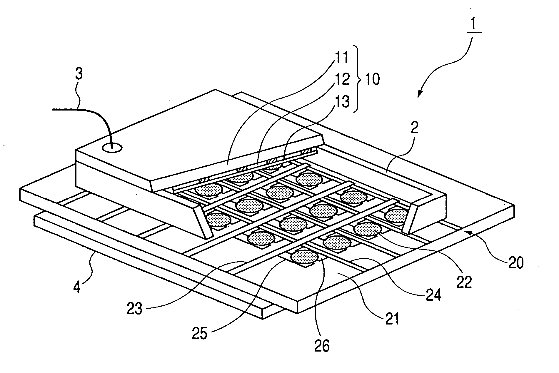
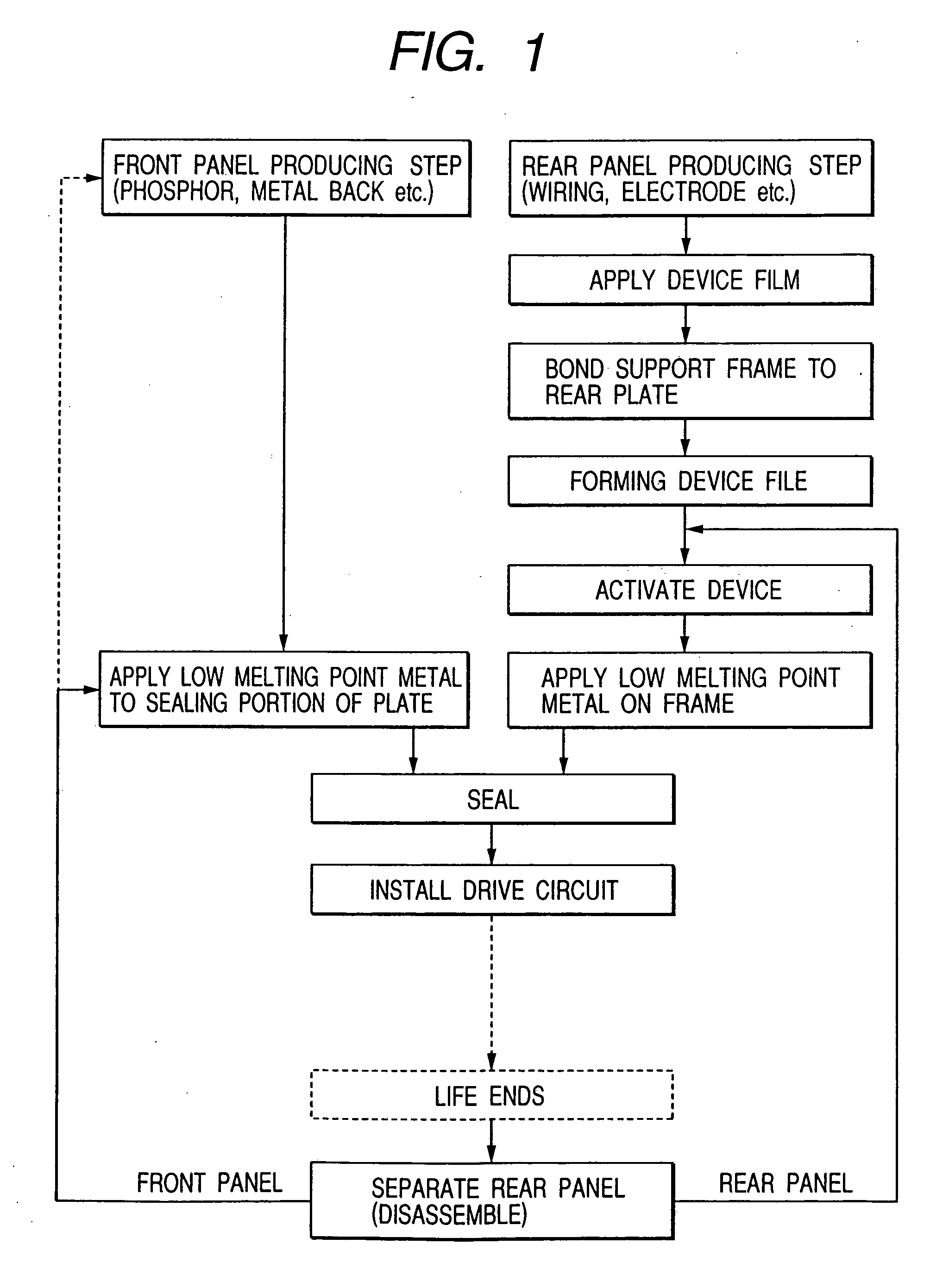
[0033] With reference to the flow of FIG. 1, detailed description will be made of a process for the SED to which the present invention is applied.

(Front Panel Producing Step)

[0034] As the front glass plate 11, 2.8 mm-thick glass of PD-200 (manufactured by Asahi Glass Co., Ltd.) that is low in the content of alkaline components is used. After the front glass plate 11 is sufficiently washed, 0.1 μm of ITO (indium-tin oxide) is deposited thereon by sputtering to form a transparent electrode. Subsequently, a phosphor film is applied thereto by printing, and surface smoothing processing called filming is performed to form the phosphor 12. Note that the phosphor 12 is structured by arranging stripe-shaped phosphors in three colors of red, green, and blue so as to be spaced alternately with black conductive materials (black stripes). In addition, the metal back 13 is formed using an aluminum thin film on the phosphor 12 to have a thickness of 0.1 μm by sputtering.

(Rear Panel Producing...


PUM


Abstract

In a recycling method for an image display apparatus including a vacuum container structured by sealing a front panel having a phosphor and a rear panel having an electron emitter for irradiating electrons onto the phosphor, the rear panel is separated from the vacuum container, the electron emitter on the rear panel is recovered, and then the rear panel is sealed again to thereby reconstruct the vacuum container.

Description

[0001] This application is a continuation of application Ser. No. 10 / 622,431, filed on Jul. 21, 2003, now U.S. Pat. No. 6,988,921.BACKGROUND OF THE INVENTION [0002] 1. Field of the Invention [0003] The present invention relates to a flat-type image display apparatus structured by arranging a front panel and a rear panel via a frame, and more particularly to a recycling method for an image display apparatus whose life has ended. [0004] 2. Related Background Art [0005] In recent years, with development of larger-screen image display apparatuses being underway, so-called flat panel displays that are light and thin have been receiving attention as an alternative to cathode ray tubes (hereinafter, referred to as CRTs) that are bulky and heavy. Examples of the flat panel displays whose research and development are well underway in recent years include a liquid crystal display (hereinafter, referred to as LCD) and a plasma display panel (hereinafter, referred to as PDP). There still remain...

Claims


Application Information

Patent Timeline
Patent Type & Authority Applications(United States)
IPC IPC(8): H01J9/50H01J9/24H01J9/52
CPCH01J9/241H01J9/52Y02W30/82
Inventor MIURA, TOKUTAKAHASEGAWA, MITSUTOSHITOKIOKA, MASAKISHIGEOKA, KAZUYA
Owner CANON KK
Why Eureka
Try Eureka