
Small vessel stent designs

Inactive Publication Date: 2006-06-22
BIOSENSORS INT GROUP
View PDF99 Cites 76 Cited by
  • Summary
  • Abstract
  • Description
  • Claims
  • Application Information

AI Technical Summary

Benefits of technology

[0014] Regarding the stent itself, each embodiment is suited for small vessel use by virtue of various features. Many of the stents according to the present invention offer designs for minimizing stent wall thickness. Reduced wall thickness minimizes the space occupied necessarily occupied by the stent in the delivery system. Conserving space is very important in designing delivery systems that are able to access small vessels. As such, stents according to the present invention have a strut thickness-to-strut width ratio around about 1:1, and generally not more than about 3:2.
[0021] In addition, when the struts are compressed as described, and the stent reaches its minimum diameter but the struts do not contact, or have minimal contact as desired, the body has a better chance of maintaining a cylindrical profile. In comparison, where strut members are configured such that substantial contact is expected upon full compression such as in the '807 patent or otherwise (especially when they have rounded edges as common to electropolished prostheses), they will tend to ride up over one another. Even when they do not, the propensity to do so will result in additional forces normal to the surface of the compressed stent that can increase engagement with an overriding sheath. In addition, deformation of the sheath material can even result in a positive interlock between the parts as portions of the stent protrude outward. Such conditions are avoided by the aforementioned stent according to the present invention.
[0036] It is noted that without the material stress levelplateau”, a stent constructed of the material may be the case in some instances require higher hold-down forces. However, such a stent can be designed to operate in a vessel or other hollow body conduit at greater compression (both in terms of percentage from unconstrained and / or overall force) without concern of collapse upon reaching a point where a small amount of additional force will drive large-scale compression. In the alternative, it may be possible to design a stent to deliver comparable in-vessel radial forces as a typical NITIONOL stent, while using less material. Still further, with a stent that requires greater compression to generate the same forces, the setup may be more forgiving of tapered vessel anatomy because the forces generated will be relatively more evenly distributed despite unequal compression over the length of the stent.
[0042] Such a stent is able to be highly compressed, up to about 7% or 8% strain like typical NITINOL, and yet offer higher deployed stresses by enabling in-situ strain rates over 1.5% (i.e., into a range where other superelastic NiTi stents undergo a martinsitic phase change at body temperature, thereby limiting radial force potential and implicating fatigue issues).

Problems solved by technology

Problems encountered with known delivery systems include drawbacks ranging from failure to provide means to enable precise placement of the subject prosthetic, to a lack of space efficiency in delivery system design.
Space inefficiency in system design prohibits scaling the systems to sizes as small as necessary to enable difficult access or small-vessel procedures (i.e., in tortuous vasculature or vessels having a diameter less than 3 mm, even less than 2 mm).
While ease of collapsing the stent for loading in the delivery system can be achieved using longer-length struts in a stent design, doing so results in loss of radial force that the stent can withstand or exert when set within a vessel or other hollow body lumen.
Internal forces can be a significant issue with respect to system actuation.

Method used


Image

  • Small vessel stent designs
  • Small vessel stent designs
  • Small vessel stent designs

Examples


Embodiment Construction

[0058] Various exemplary embodiments of the invention are described below. Reference is made to these examples in a non-limiting sense. They are provided to illustrate more broadly applicable aspects of the present invention. Various changes may be made to the invention described and equivalents may be substituted without departing from the true spirit and scope of the invention. In addition, many modifications may be made to adapt a particular situation, material, composition of matter, process, process act(s) or step(s) to the objective(s), spirit or scope of the present invention. All such modifications are intended to be within the scope of the claims made herein.

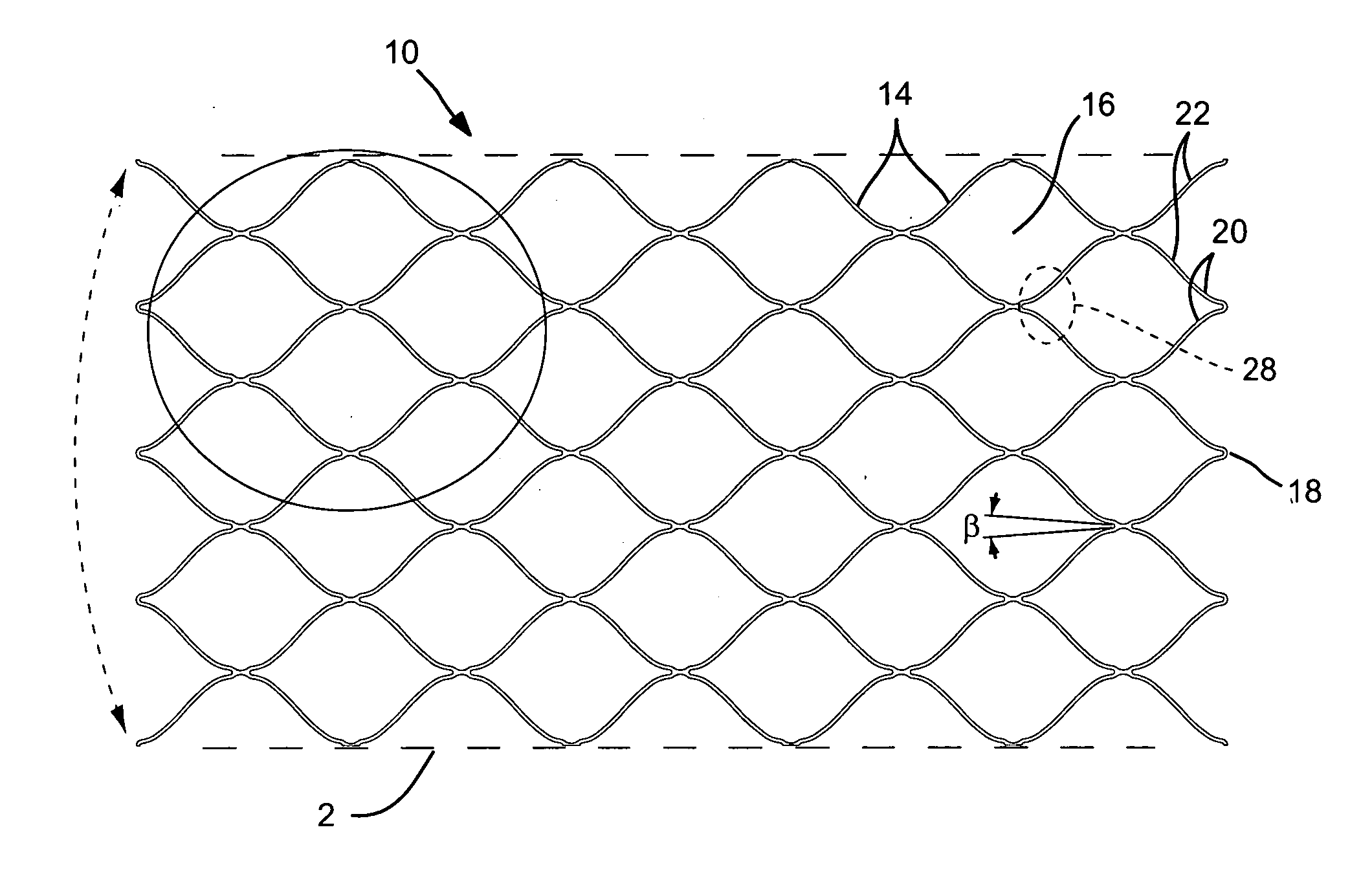
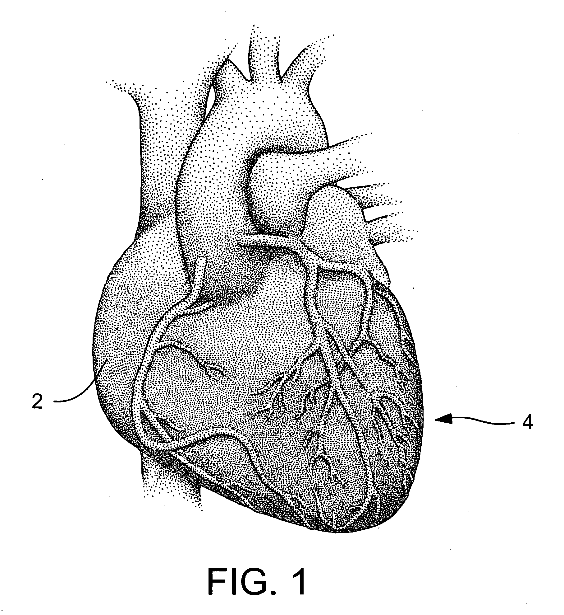
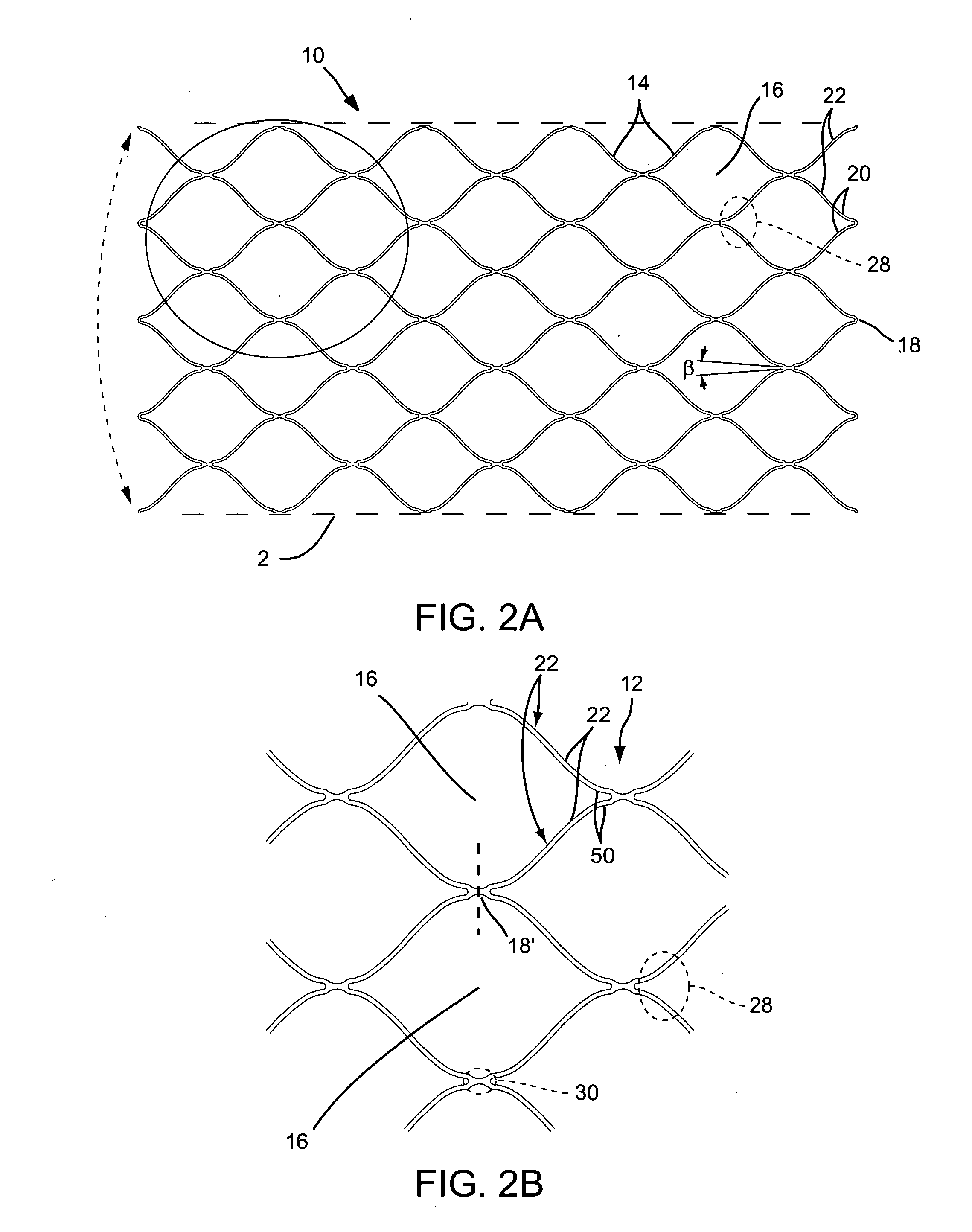
[0059] In light of this framework, FIG. 1 shows a heart 2 in which its vessels may be the subject of one or more angioplasty and / or stenting procedures. To date, however, significant difficulty or impossibility is confronted in reaching smaller coronary arteries 4. If a stent and a delivery system could be provided for...


PUM


Abstract

Medical device and methods for delivery or implantation of prostheses within hollow body organs and vessels or other luminal anatomy are disclosed. The subject technologies may be used in the treatment of atherosclerosis in stenting procedures.

Description

CROSS REFERENCE [0001] This filing claims the benefit provisional patent application Ser. No. 60 / 619,437, entitled “Small Vessel Stent Designs” filed Oct. 14, 2004 the entirety of which is incorporated by reference.BACKGROUND [0002] Implants such as stents and occlusive coils have been used in patients for a wide variety of reasons. One of the most common “stenting” procedures is carried out in connection with the treatment of atherosclerosis, a disease which results in a narrowing and stenosis of body lumens, such as the coronary arteries. At the site of the narrowing (i.e., the site of a lesion) a balloon is typically dilatated in an angioplasty procedure to open the vessel. A stent is set in apposition to the interior surface of the lumen in order to help maintain an open passageway. This result may be effected by means of scaffolding support alone or by virtue of the presence of one or more drugs carried by the stent aiding in the prevention of restenosis. [0003] Various stent d...

Claims


Application Information

Patent Timeline
IPC IPC(8): A61F2/06
CPCA61F2/91A61F2/915A61F2230/0013A61F2002/91541A61F2002/91558A61F2/95
Inventor DEBEER, NICHOLAS C.BECKING, FRANK P.
Owner BIOSENSORS INT GROUP
Learn More