Polarized tape dispenser

a tape dispenser and polarized technology, applied in the field of tape dispensers, can solve the problems of difficult restriction, difficulty in pulling off a roll by hand, and difficulty in maneuvering it around the package, and achieve the effect of manufacturing more economically

Inactive Publication Date: 2006-06-29
KITARU INNOVATIONS
View PDF5 Cites 0 Cited by
  • Summary
  • Abstract
  • Description
  • Claims
  • Application Information

AI Technical Summary

Benefits of technology

[0010] Another feature of the improved tape dispenser is molding the tape roll hub as a one-piece member, enabling it to be manufactured more economically by eliminating secondary assembly of multiple components.
[0011] A further feature of the invention is to form the hub as a two or three component member, which enables existing hubs to be utilized requiring only a separate polarizing ring to be formed and mounted thereon, which enable the hubs to be compatible with current tape winding machinery and methodology.
[0013] Still another feature of the invention is to enable the dispenser frame and tape roll hubs to be molded inexpensively of plastic material in various widths, which provides for a relatively simple and durable tape dispenser, yet one which insures correct orientation of the tape roll on the frame for proper positioning of the adhesive side of the tape to insure that the dispenser is used as intended.

Problems solved by technology

This type of tape is typically two inches wide and is fairly difficult to pull off a roll by hand and maneuver it into position around the package.
Many of these devices, however, experience a number of problems in their usage, one of which is the correct position of the roll of adhesive tape on the frame so that the adhesive side of the tape is properly oriented for correctly dispensing the tape from the dispenser onto a package or other surface.
Dispenser having the same size hub mounts and corresponding tape hubs make such a restriction difficult.

Method used


Image

  • Polarized tape dispenser
  • Polarized tape dispenser
  • Polarized tape dispenser

Examples


first embodiment

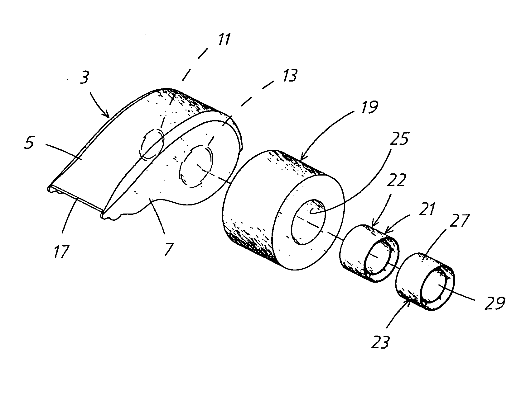
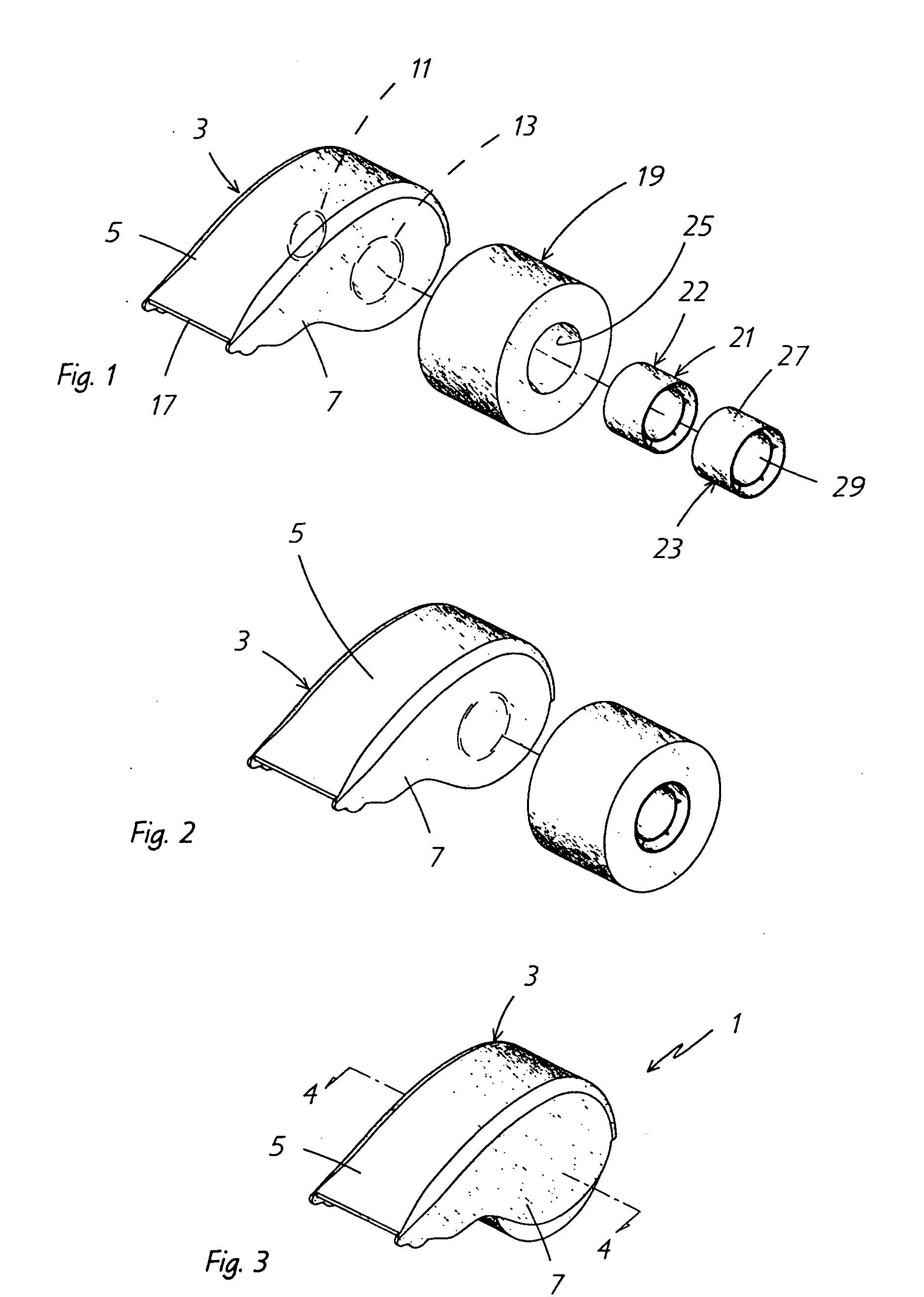
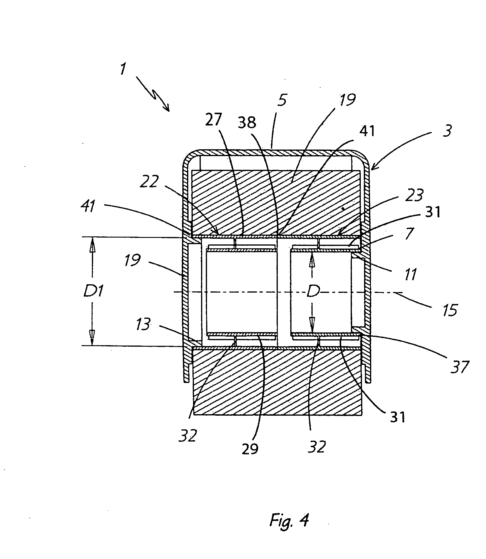
[0046]FIGS. 1-8 show the improved tape dispenser, which is indicated generally at 1. Tape dispenser 1 includes a frame indicated generally at 3. Frame 3 includes a curved upper wall 5 and a pair of curved irregularly-shaped side walls 7 and 9, each of which is formed with a hub mount 11 and 13, respectively, which extend inwardly toward each other as shown in FIG. 4. Each hub mount has an annular configuration and has their centers lie on a common axis 15. In accordance with one of the features of the invention, hub mount 11 is of a smaller diameter than that of hub mount 13 as shown particularly in FIG. 4. The configuration of frame 3 is similar to commonly used tape dispensers, but has the unique feature of the unequal hub mounts, preferably formed integrally thereon. Preferably, frame 3, including the hub mounts, is a one-piece member molded inexpensively of plastic material, and may have a serrated blade (not shown) mounted or formed on a discharge end 17 of curved upper wall 5....

embodiment 70

[0052] Embodiment 70 enables identical hub members to be produced and utilized, thereby reducing inventory cost and manufacturing costs, but does require a second component in annular end member 80, which requires another procedure for mounting it within the open end of one of the hub members. Again, flanges 78 terminate axially inwardly from the peripheral edge of the hub members a sufficient distance to permit the insertion of end member 80 in one end thereof, and the insertion of hub mount 13 in an opposite end of the other hub member as shown in FIG. 25.

[0053] A fifth embodiment of the polarized tape dispenser is indicated generally at 90, and shown in FIGS. 28-30. Embodiment 90 includes a tape roll 19 and a two-piece hub indicated generally at 92. Hub 92 includes a cylindrical-shaped body 93 having an outer cylindrical surface 94 about which the tape is wound, which terminates in open ends 95 and 96. An annular end member 98 has an outer diameter D1 enabling it to be telescopic...


PUM


Abstract

A tape dispenser having a frame and a pair of opposed, unequal diameter hub mounts for rotatably mounting an adhesive tape roll thereon. The tape roll includes a hub about which the tape is wound and has first and second open ends with unequal diameter openings. Each of the hub mounts is compatible in diameter with a respective one of the hub open ends requiring the tape roll to be correctly mounted on the hub mounts to insure the adhesive side of the tape be properly oriented.

Description

CROSS REFERENCE TO RELATED APPLICATIONS [0001] This application is a continuation of U.S. Standard Utility application Ser. No. 10 / 651,514, filed Aug. 28, 2003; which application claimed priority from U.S. Provisional Application Ser. No. 60 / 460,581, filed Apr. 4, 2003, the entire specifications of which are incorporated herein by reference.BACKGROUND OF THE INVENTION [0002] 1. Technical Field [0003] The invention relates to tape dispensers. More particularly, the invention relates to hand-held tape dispensers adapted to dispense adhesive tape. Specifically, the invention relates to a hand-held tape dispenser that has a polarized hub configuration to prevent the user from installing the tape roll in an inverted, incorrect orientation on the supporting frame. [0004] 2. Background Information [0005] There are numerous types of adhesive tapes that have a wide variety of uses. A frequently used type of adhesive tape is packaging tape that is used to secure the flaps of boxes and package...

Claims


Application Information

Patent Timeline
Patent Type & Authority Applications(United States)
IPC IPC(8): B65D85/02B65H35/00
CPCB65H35/0026B65H35/0073
Inventor CHANDARIA, ASHOK V.
Owner KITARU INNOVATIONS
Why Eureka
Try Eureka