
Method and system for controlling a display device

a display device and control method technology, applied in the field of wireless devices, can solve the problems of system inconvenient and time-consuming, technology is becoming increasingly sophisticated, and the means of interacting with it are not availabl

Inactive Publication Date: 2006-06-29
SATURN LICENSING LLC
View PDF29 Cites 50 Cited by
  • Summary
  • Abstract
  • Description
  • Claims
  • Application Information

AI Technical Summary

Benefits of technology

This solution provides a more natural and accurate method for interacting with display devices, reducing errors and improving user experience by allowing precise cursor control with scaled movements, enhancing the usability of interactive television features.

Problems solved by technology

However, while television technology is becoming increasingly sophisticated, the means of interacting with it are not.
Many users find this system inconvenient and time consuming and would prefer a control interface that looks and functions in a manner similar to a web browser interface, with which many of the users are already familiar.
However, the directional buttons used with prior art television control devices are not well suited for controlling the movement of a cursor.
This is inconvenient for many users because the user has to switch between different input devices to interact with the television.
Placing a trackball on the remote controller itself eliminates the need for a dedicated cursor controller, but is difficult for many users to operate as well.
However, mechanical gyroscopes are subject to a phenomenon called bias drift which results in significant margins of error over time.
Each calculation of angle introduces a margin of error, and as the angles are added together, this margin of error becomes greater and greater and can, over time, make it practically impossible to accurately determine angular displacement.
However, this device does not determine a point on a display device at which the controller is pointed, but relies upon being able to sense the position of the controller itself.
Additionally, this controller relies upon ranging techniques, the range and resolution of the device is limited.

Method used


Image

  • Method and system for controlling a display device
  • Method and system for controlling a display device
  • Method and system for controlling a display device

Examples


Embodiment Construction

[0025] Reference will now be made in detail to embodiments of the present invention, examples of which are illustrated in the accompanying drawings. While the present invention will be described in conjunction with the following embodiments, it will be understood that they are not intended to limit the present invention to these embodiments alone. On the contrary, the present invention is intended to cover alternatives, modifications, and equivalents which may be included within the spirit and scope of the present invention as defined by the appended claims. Furthermore, in the following detailed description of the present invention, numerous specific details are set forth in order to provide a thorough understanding of the present invention. However, embodiments of the present invention may be practiced without these specific details. In other instances, well-known methods, procedures, components, and circuits have not been described in detail so as not to unnecessarily obscure asp...


PUM


Abstract

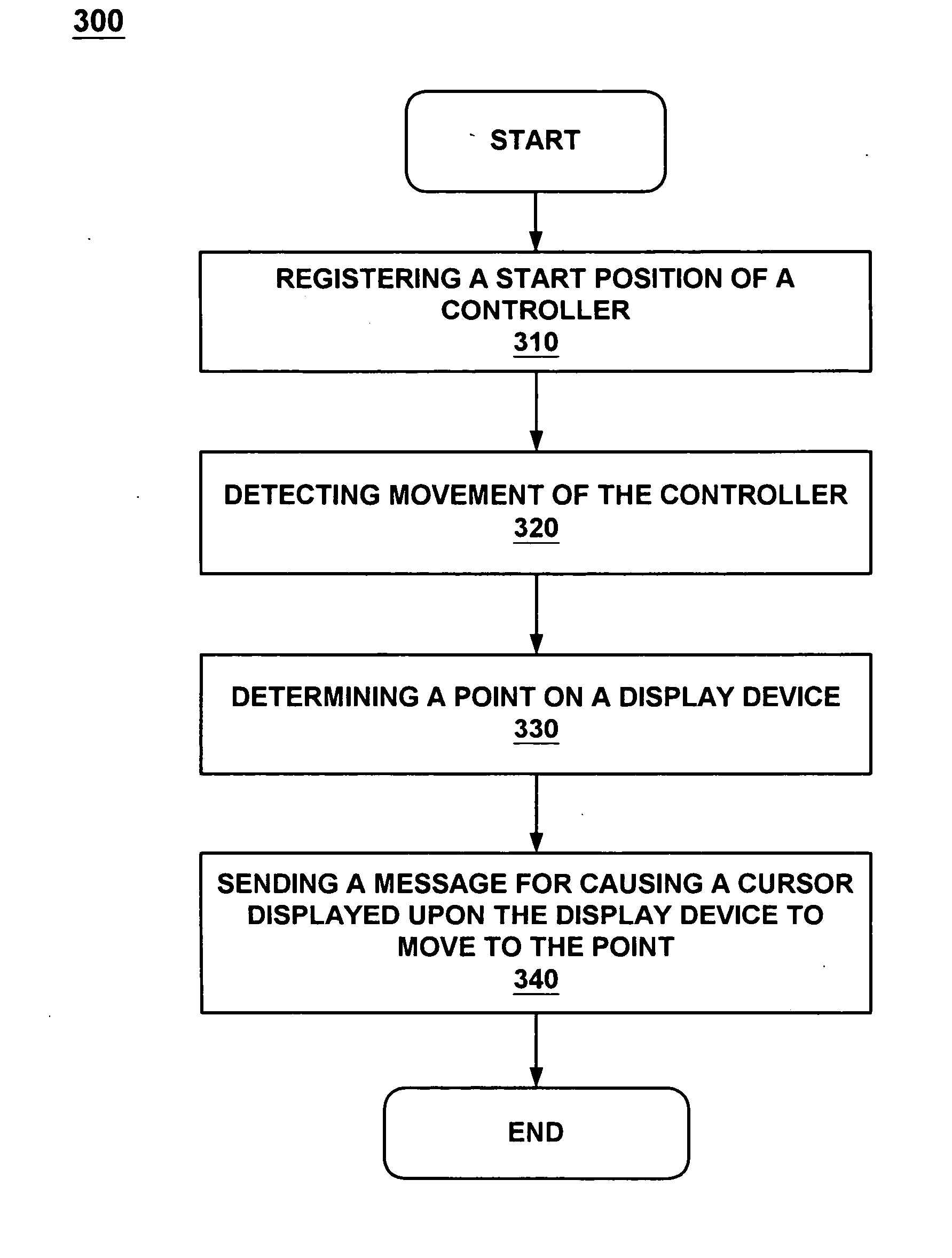
Embodiments of the present invention are directed to a method and system for controlling a display device. In one embodiment, a start position is registered which defines the first position and orientation of a remote controller relative to the position of the display device. When movement of the remote controller is detected, a second position and orientation of the remote controller is determined. A point on the display device is determined where a mathematical line extending from the front edge of the remote controller along its longitudinal axis intersects the front plane of the display device. Finally, a message is sent for causing a cursor displayed on the display device to be moved to the point where the mathematical line intersects the front plane of the display device.

Description

[0001] This patent application is a Continuation of co-pending, commonly-owned patent application Ser. No. 10 / 272,052, filed on Oct. 15, 2002, entitled “A METHOD AND SYSTEM FOR CONTROLLING A DISPLAY DEVICE”, by Thomas P. Dawson and Ryuichi Iwamura, which is incorporated herein by reference.FIELD OF THE INVENTION [0002] Embodiments of the present invention relate to the field of wireless devices. More specifically, the present invention pertains to wireless control of a cursor image for a display device. BACKGROUND OF THE INVENTION [0003] Due to current technology trends, television is becoming an increasingly interactive medium. Currently, more that 20 million users subscribe to interactive television services in the United States alone. Interactive television combines traditional television viewing with the interactivity of the Internet and the personal computer. End users can enjoy customized programming content, links to Web sites through television links, electronic mail, chat r...

Claims


Application Information

Patent Timeline
Patent Type & Authority Applications(United States)
IPC IPC(8): G09G5/08G06F3/033G06F3/042
CPCA63F2300/1006A63F2300/105G06F3/0325G06F3/0346H04N21/422
Inventor DAWSON, THOMAS P.IWAMURA, RYUICHI
Owner SATURN LICENSING LLC
Learn More