Beam joint device

a beam and joint technology, applied in the direction of elastic dampers, towers, buildings, etc., can solve the problem that the repetitive load of earthquakes is liable to break the plate member, and achieve the effect of preventing buckling

Inactive Publication Date: 2006-07-06
NIPPON STEEL CORP
View PDF9 Cites 83 Cited by
  • Summary
  • Abstract
  • Description
  • Claims
  • Application Information

AI Technical Summary

Benefits of technology

[0015] (6) According to this invention, the anti-buckling member can be arranged in such a manner as to always secure a prede...

Problems solved by technology

As a result, the repetitive load of earthquakes is liable to br...

Method used


Image

  • Beam joint device
  • Beam joint device
  • Beam joint device

Examples


second embodiment

[0066] With reference to FIGS. 6 to 9B, a second embodiment of the invention is explained. Incidentally, this embodiment is different from the first embodiment only in the shape of the first and second anti-buckling members and the remaining portions thereof are similarly configured to the corresponding portions of the first embodiment. Therefore, the similar component elements are not explained.

[0067] According to this embodiment, the first anti-buckling member 13 includes, as shown in FIGS. 9A, 9B, a rectangular plate member 21 and flanges 22 formed integrally with the edges of the plate member 21. The plate member 21 is formed with four bolt holes 15 arranged at positions corresponding to the bolt holes 3 of the lower flange 2 of the beam 1. Also in this embodiment, the first anti-sticking layer 14 is desirably attached to one side surface of the plate member 21 in advance for convenience in construction.

[0068] The plate member 21 prevents the buckling deformation along the thi...


PUM


Abstract

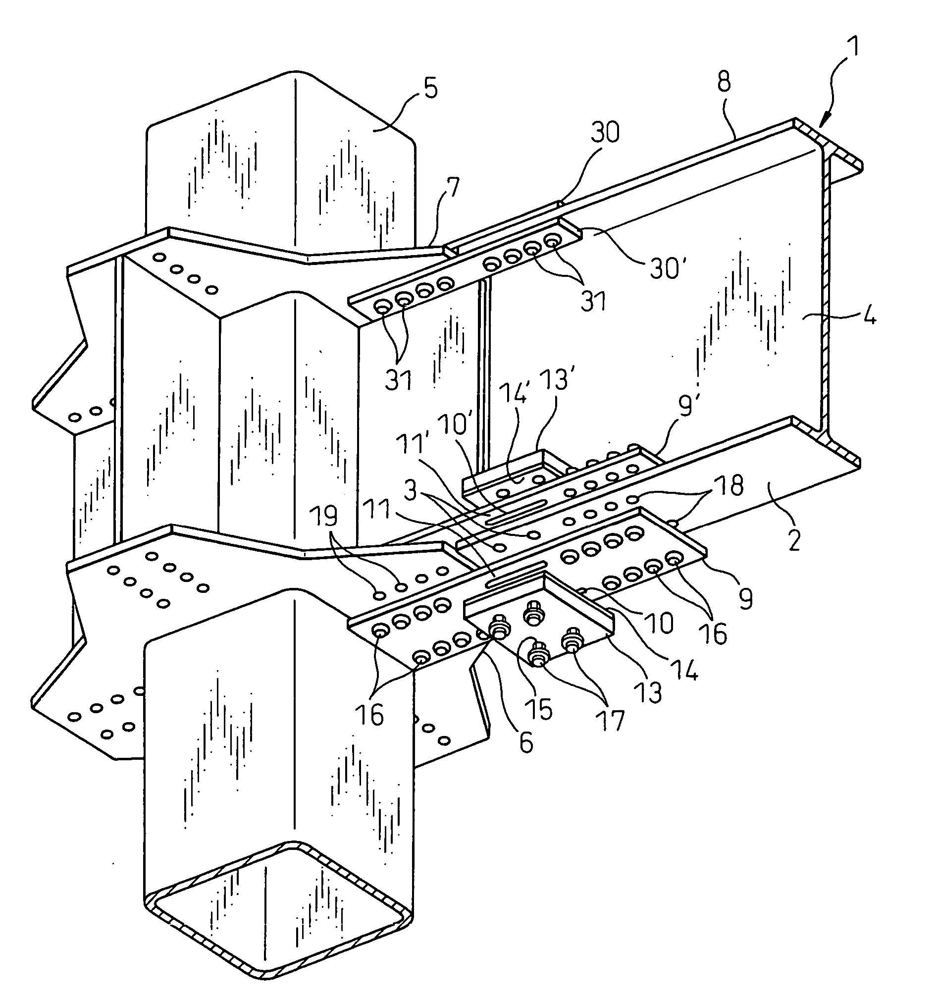
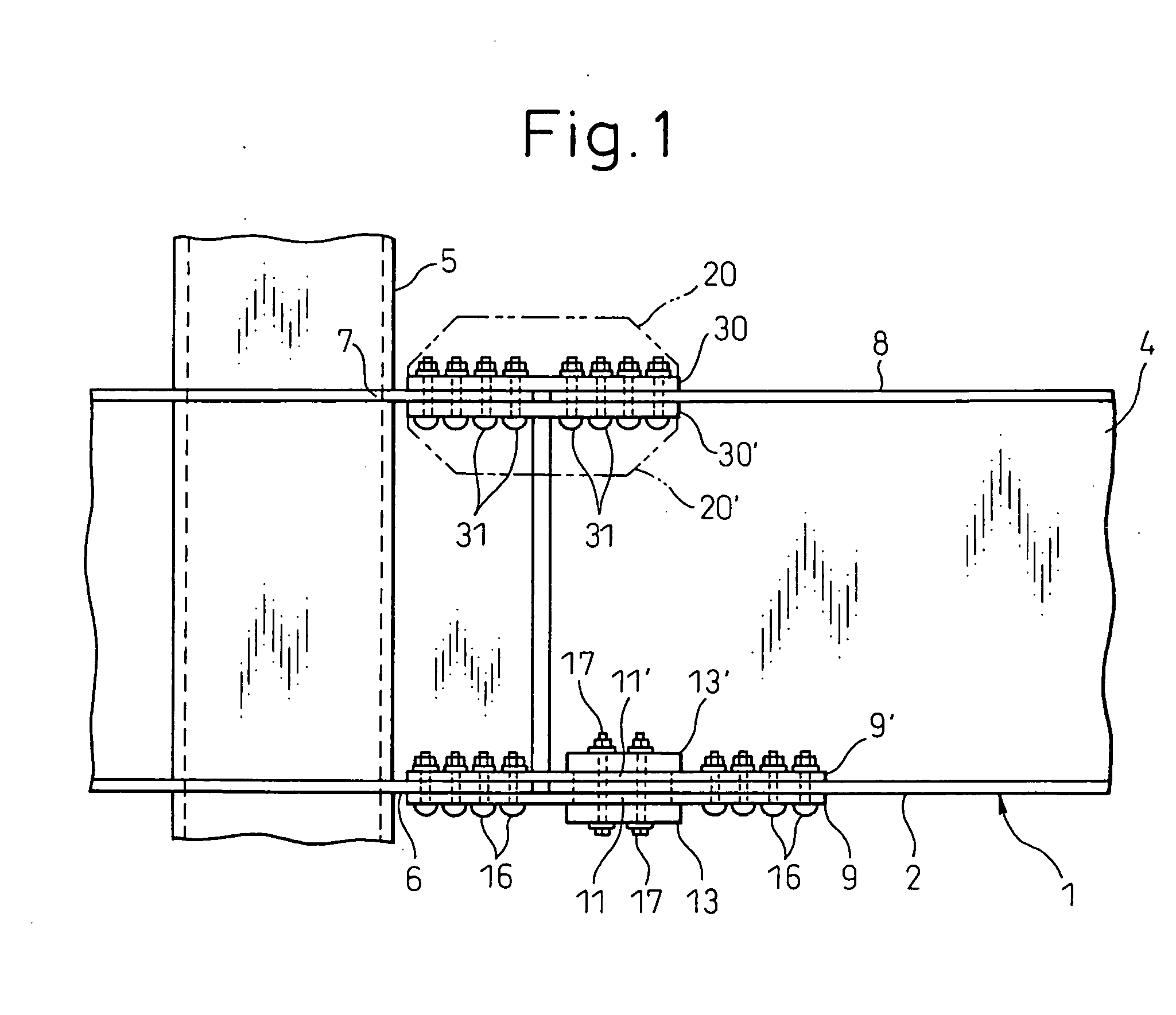
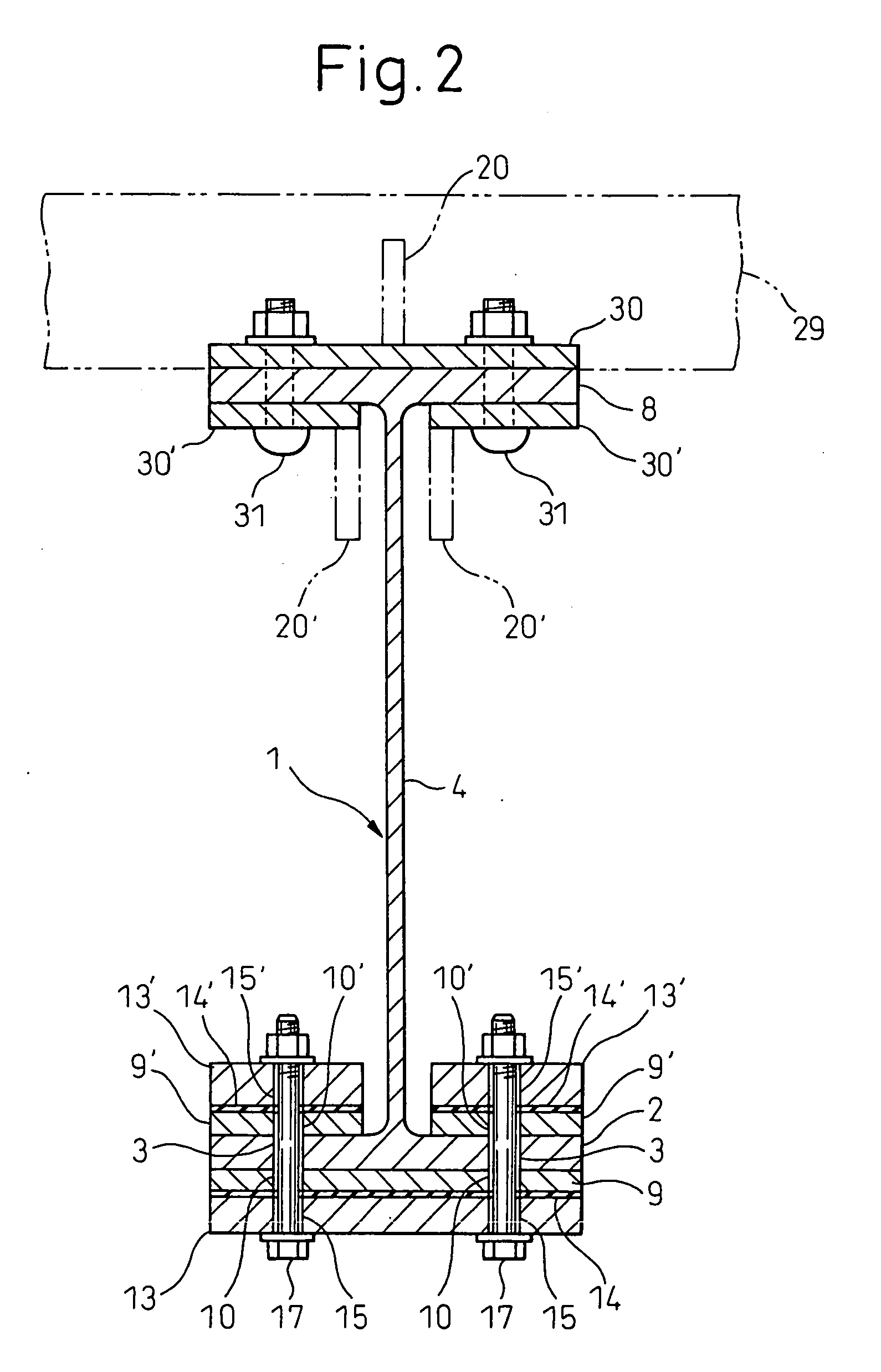
A beam joining apparatus for joining a flange 2 of a beam 1 to a flange 6 mounted on a pillar 5 includes a splice plate 9 fastened to the flanges 6, 2 of the pillar 5 and the beam 1 and having a central plastic region 11, and an anti-buckling member 13 mounted independently of the splice plate 9, on the splice plate 9, for preventing the buckling of the plastic region 11.

Description

TECHNICAL FIELD [0001] This invention relates to a beam joining apparatus for joining a beam to a pillar of an iron-frame building. BACKGROUND ART [0002] Japanese Unexamined Patent Publication No. 2000-144901 discloses a beam joining apparatus comprising a splice plate 100 shown in FIG. 16 for joining a pillar flange and a beam flange of an iron-frame building to each other. In FIG. 16, the splice plate 100 includes a plate member 102 having a narrowed central portion. A pair of reinforcing ribs 106 arranged in spaced relation, to each other, in the axial direction of the beam are fixedly attached to the plate member 102. In the plate member 102, the portion between the reinforcing ribs 106 forms a plastic region 108. Also, the plate member 102 is formed with bolt holes 104 for fastening the plate member 102 by bolts (not shown) to the pillar flange (not shown) and the beam flange (not shown). [0003] In the splice plate 100, an increased size D of the interval between the reinforcin...

Claims


Application Information

Patent Timeline
IPC IPC(8): E04H12/00E04B1/24E04B1/58F16F7/12
CPCE04B1/2403E04B2001/2415E04B2001/2442E04H9/024E04B2001/2454E04B2001/2457E04B2001/2448
Inventor SUZUKI, KAZUAKIMAEDA, YASUSHINAKATA, YASUHIRONAKAMURA, HIROSHITAKEUCHI, TORU
Owner NIPPON STEEL CORP
Why Eureka
Try Eureka