
Piezoelectric stack compression generator

a stack compression and generator technology, applied in the direction of generators/motors, mechanical equipment, machines/engines, etc., can solve the problem of challenging piezoelectric generator developmen

Inactive Publication Date: 2011-12-01
INNOWATTECH
View PDF12 Cites 49 Cited by
  • Summary
  • Abstract
  • Description
  • Claims
  • Application Information

AI Technical Summary

Benefits of technology

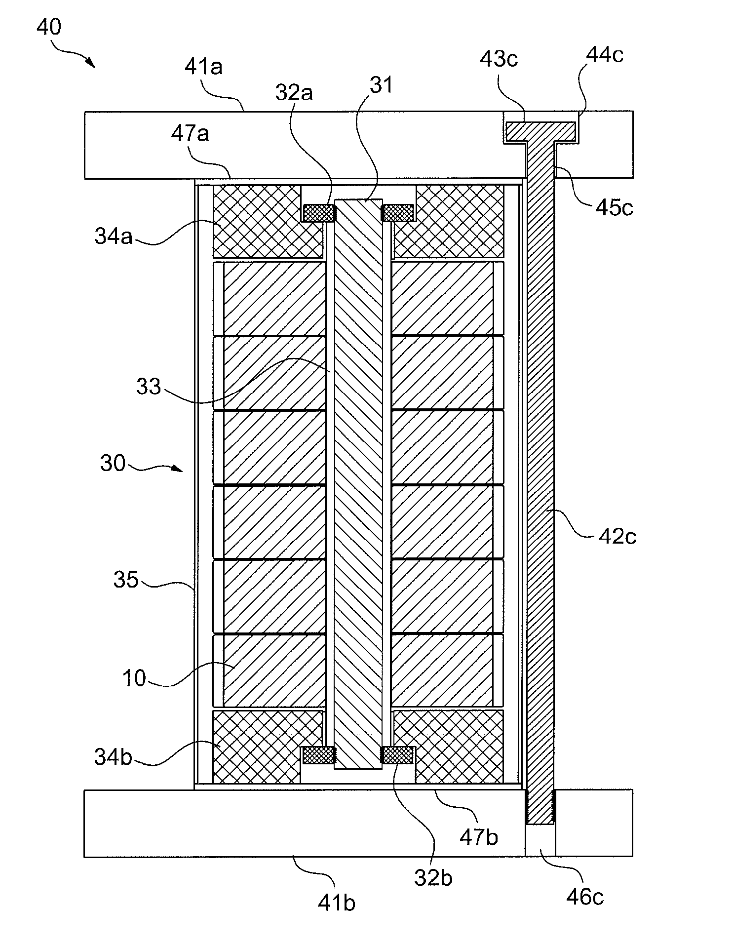
[0031]A stack of piezoelectric elements, in the form of an elongated rod divided in to segments, for generating electric energy in response to compressive stress is provided comprising: piezoelectric elements stacked one on top of the other such that electrodes of same polarity of adjacent disks are touching A holding structure, such as a screw holds the piezoelectric elements together between a top and a bottom end pieces which transfer mechanical compressive stress to the elements in the stack. The holding structure accepts shear stresses, provides preloading stress on the stack and prevents buckling of the stack under pressure. A recess in the end piece, deeper than the head of the screw, ensures that load, placed on the stack, will compress the piezoelectric elements and not on the screw.
[0033]In some embodiments, inert disks or rings are added to the structure, for example to adjust for the structure's length or to be used as electrodes or to add flexibility to the structure.
[0043]In some embodiments the stack further comprises a holding structure, stabilizing said stack against out of plate displacements.

Problems solved by technology

The paper points out that developing piezoelectric generators is challenging because of their poor source characteristics (high voltage, low current, high impedance) and relatively low power output.

Method used


Image

  • Piezoelectric stack compression generator
  • Piezoelectric stack compression generator
  • Piezoelectric stack compression generator

Examples


Embodiment Construction

[0083]The present invention relates to an energy harvesting apparatus having stack piezoelectric elements, and system, method and applications for implementation of said apparatus.

[0084]Before explaining at least one embodiment of the invention in detail, it is to be understood that the invention is not limited in its application to the details of construction and the arrangement of the components set forth in the following description or illustrated in the drawings. The invention is capable of other embodiments or of being practiced or carried out in various ways. It can be applied for any surface where mechanical load can be transferred efficiently into electrical load.

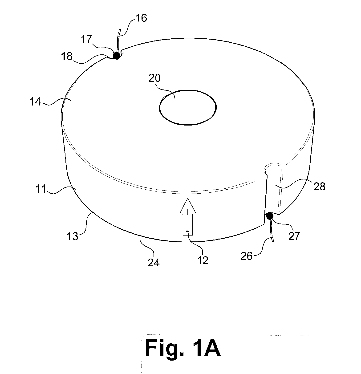
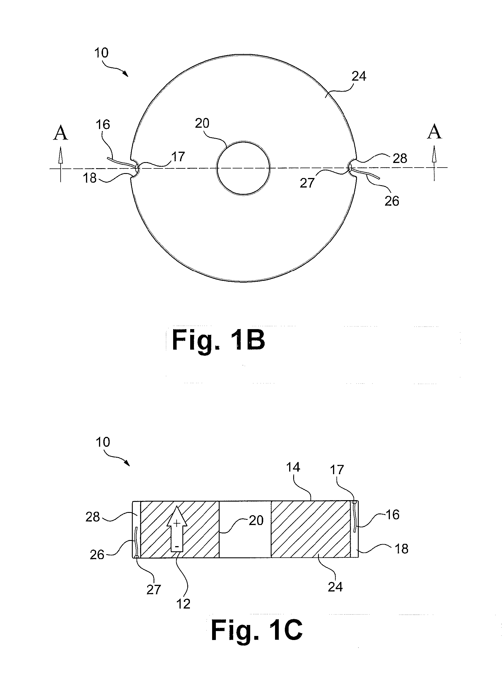
[0085]FIG. 1a schematically depicts an isometric view of a piezoelectric disk 10 according to an exemplary embodiment of the current invention.

[0086]Washer shaped bioelectric element 10 comprises a round disk, rings 11 made of piezoelectric material polled in the direction depicted by the arrow 12 such that compress...


PUM


Abstract

A stack of piezoelectric elements, in the form of an elongated rod divided in to segments, for generating electric energy in response to compressive stress is provided comprising: piezoelectric elements stacked one on top of the other such that electrodes of same polarity of adjacent disks are touching A holding structure, such as a screw holds the piezoelectric elements together between a top and a bottom end pieces which transfer mechanical compressive stress to the elements in the stack. The holding structure accepts shear stresses, provides preloading stress on the stack and prevents buckling of the stack under pressure. A recess in the end piece, deeper than the head of the screw, ensures that load placed on the stack will compress the piezoelectric elements and not on the screw.

Description

FIELD OF THE INVENTION[0001]The present invention relates to an energy harvesting apparatus having stack piezoelectric elements, and system, method and applications for implementation of said apparatus.BACKGROUND OF THE INVENTION[0002]Piezoelectricity is the ability of certain materials to develop an electrical charge proportional to an applied mechanical stress. The converse effect can also be seen in these materials where strain is developed proportional to an applied electrical field. The Curie's originally discovered it in the 1880's. Piezoelectric materials are the most well known active material typically used for transducers as well as in adaptive structures. Mechanical compression or tension on a poled piezoelectric element changes the dipole moment, creating a voltage. Compression along the direction of polarization, or tension perpendicular to the direction of polarization, generates voltage of the same polarity as the poling voltage. Tension along the direction of polariz...

Claims


Application Information

Patent Timeline
Patent Type & Authority Applications(United States)
IPC IPC(8): H02N2/18H01L41/053F03G7/08H01L41/083H10N30/50H10N30/30H10N30/88
CPCH01L41/0835H02N2/18H01L41/113F03G7/08H10N30/886H10N30/505H10N30/30
Inventor ABRAMOVICH, HAIMMILGROM, CHARLESHARASH, EUGENYEDERY-AZULAY, LUCYAMIT, URI
Owner INNOWATTECH
Learn More