Robotic catheter device cartridge

a robotic catheter and cartridge technology, applied in the field of robotic catheter systems, can solve the problems of varying ailments and even death, and achieve the effects of minimizing and/or eliminating radiation exposure, minimizing and/or eliminating procedural variability

Active Publication Date: 2009-10-01
ST JUDE MEDICAL ATRIAL FIBRILLATION DIV
View PDF56 Cites 54 Cited by
  • Summary
  • Abstract
  • Description
  • Claims
  • Application Information

AI Technical Summary

Benefits of technology

[0008]It is desirable to provide a system and method for precise and dynamic automated control of a catheter and its related components. In particular, it is desirable to provide a system and method for precise and dynamic automated control, for example, for diagnostic, therapeutic, mapping and ablativ

Problems solved by technology

Arrhythmia can create a variety of dangerous conditions including irregular heart rates, loss of synchronous

Method used


Image

  • Robotic catheter device cartridge
  • Robotic catheter device cartridge
  • Robotic catheter device cartridge

Examples


first embodiment

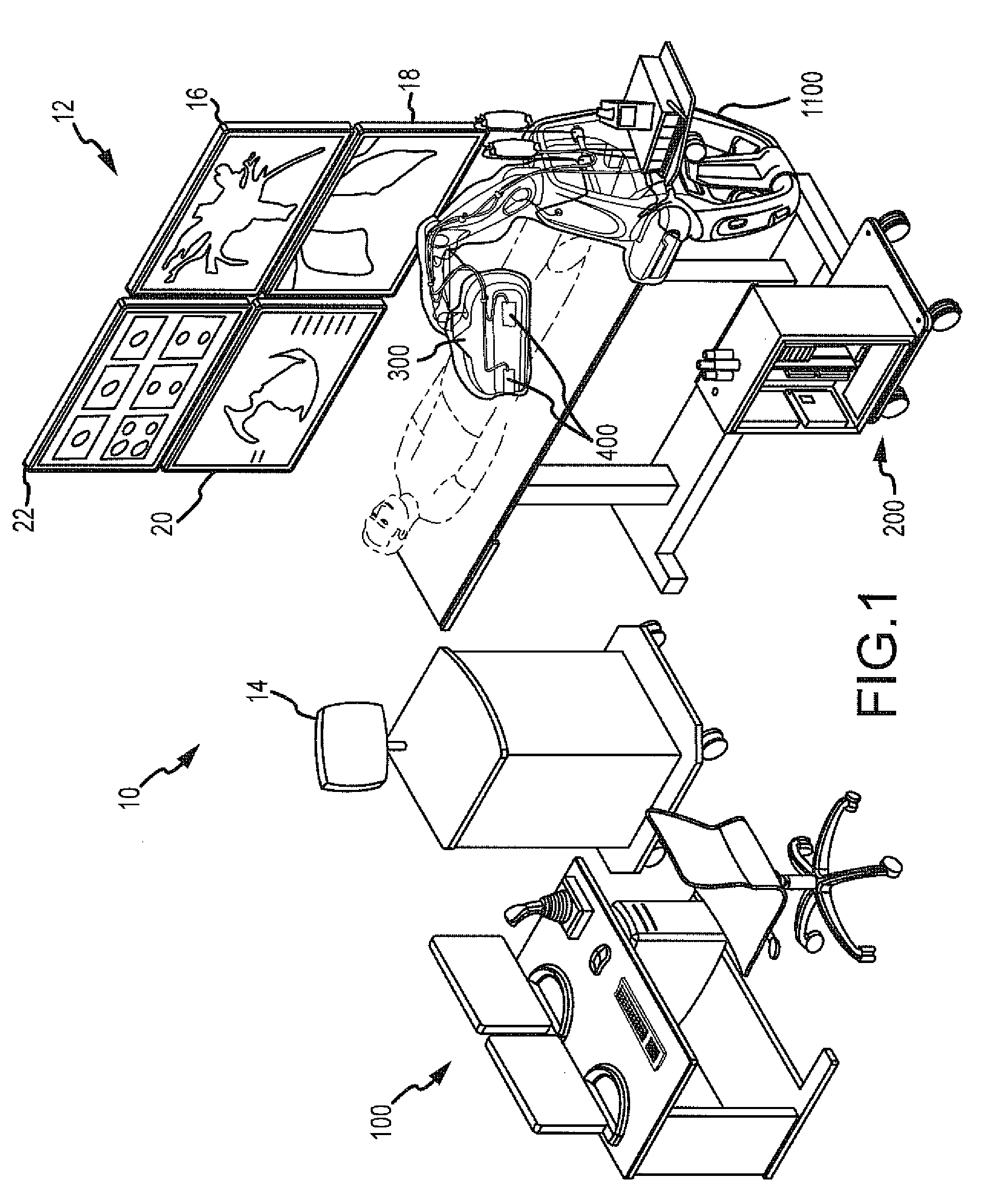
[0059]As generally shown in FIGS. 1 and 3a-3e and discussed in greater detail below and in commonly owned and copending application titled “Robotic Catheter Manipulator Assembly,” a manipulator assembly 302 may respectively include both catheter and sheath manipulator mechanisms 304, 306. In this arrangement, the catheter and sheath manipulator mechanisms 304, 306 may be aligned such that the catheter can pass through the sheath in a coaxial arrangement. Each mechanism 304, 306 may be further capable of independent advancement / retraction (shown generally as directions D1 and D2) and independent four-wire steering control (e.g., eight total steering wires, comprising four sheath control wires and four catheter control wires), as discussed in detail below.

[0060]With a configuration of robotic catheter system 10, such as shown in FIGS. 1 and 3a-3e, there will be relative travel of a first embodiment of catheter and sheath cartridges 402, 404 and relative movement associated with a port...

second embodiment

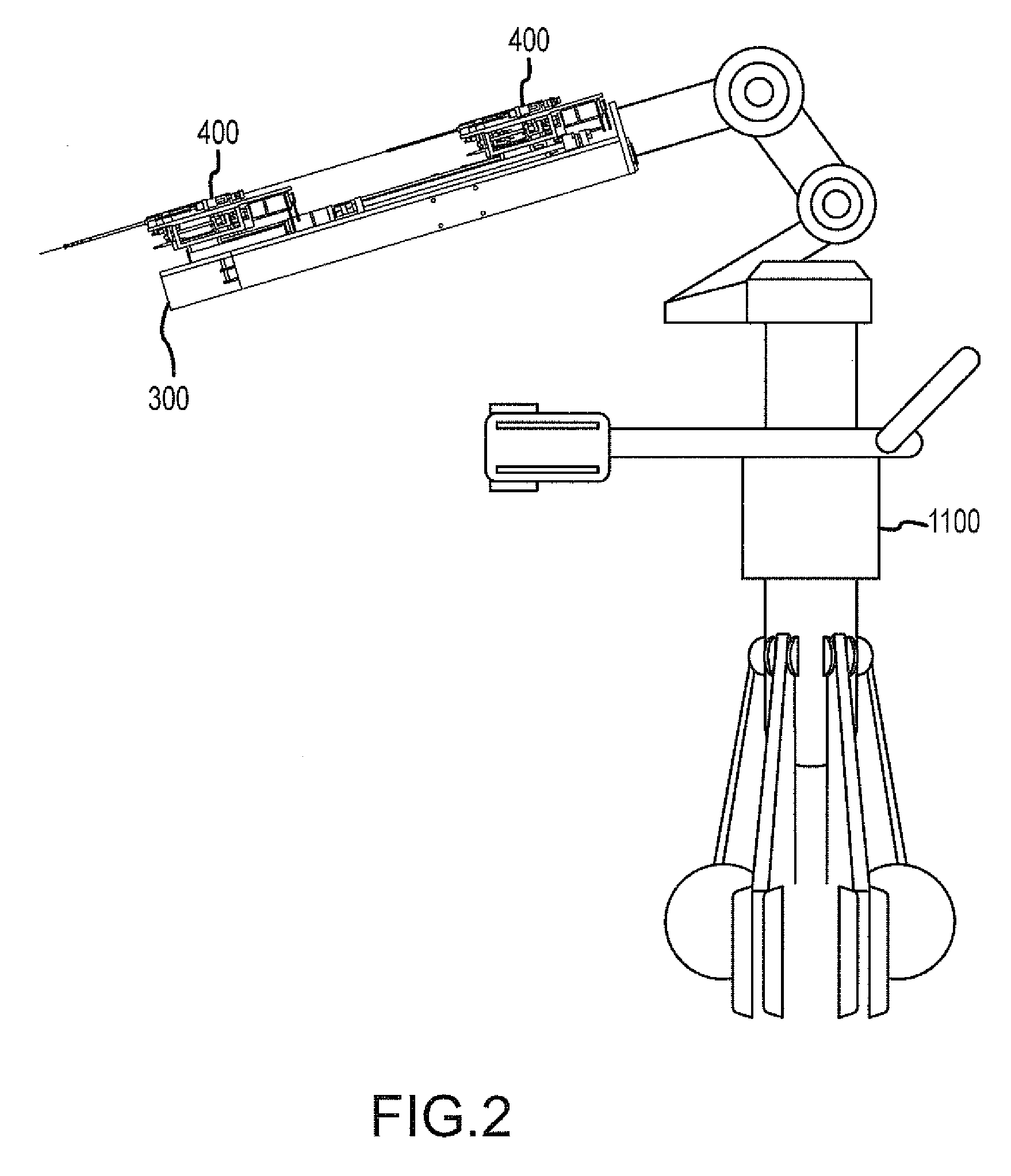
[0076]Referring to FIGS. 1, 2 and 9a-11e, robotic catheter manipulator assembly 500 will be described in detail.

[0077]As generally shown in FIGS. 1, 2 and 9a-11e, robotic catheter system 10 which includes one or more robotic catheter manipulator assemblies 300, includes the second embodiment of robotic catheter manipulator assembly 500 including both catheter and sheath manipulation mechanisms 504, 506 for manipulating, for example, a second embodiment of catheter and sheath cartridges 602, 604 (see FIGS. 11a-11e). Manipulator assembly 500 may include interconnected / interlocking manipulation bases 508, 510 for catheter and sheath cartridges 602, 604, and likewise may include electrical “handshake” functionality as discussed below. Each interlocking base 508, 510 may be capable of travel in the longitudinal direction of the catheter / sheath (D1, D2 respectively). In an embodiment, D1 and D2 may each represent a translation of approximately 8 linear inches. As shown in FIG. 9a (similar...

third embodiment

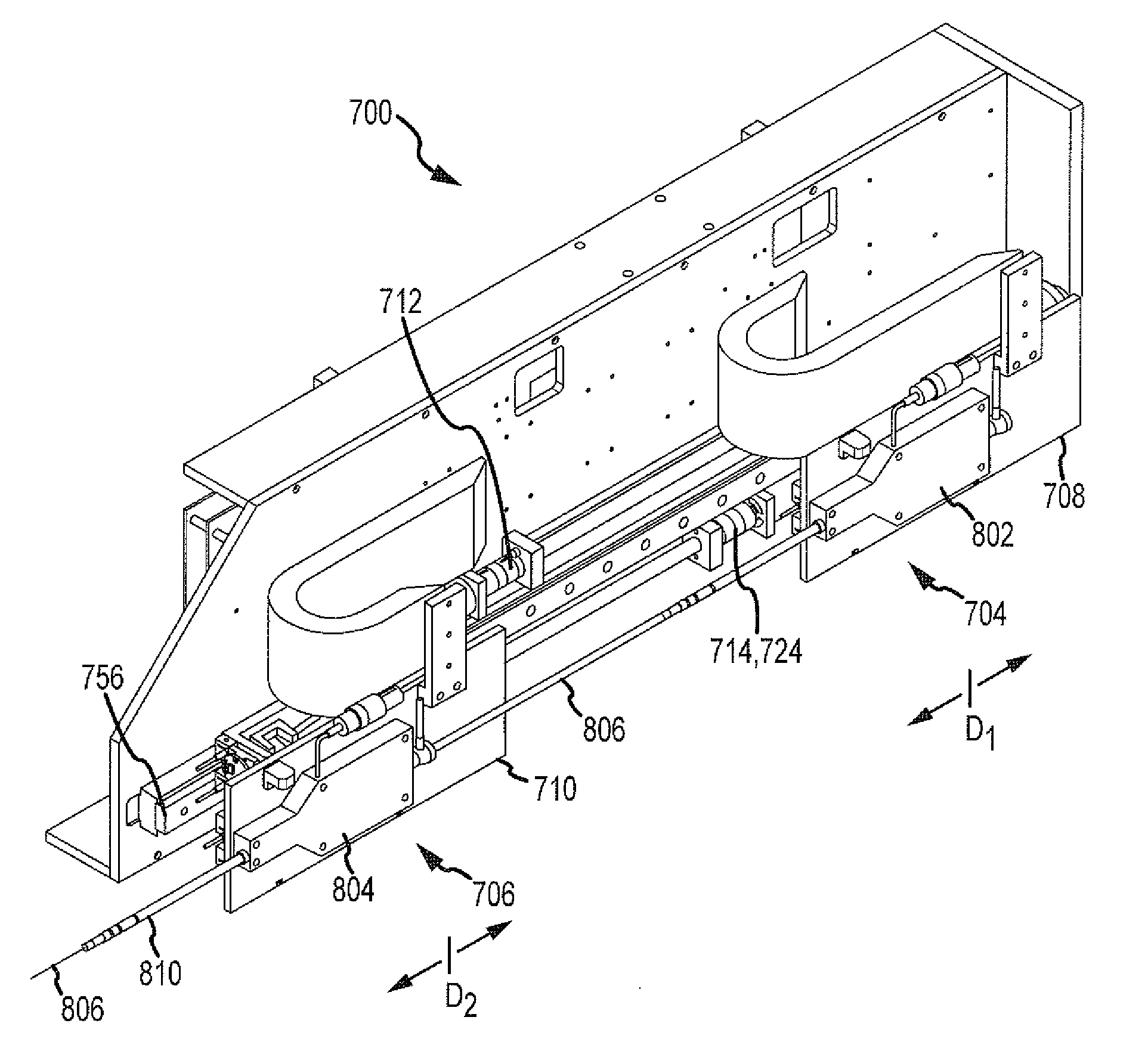
[0089]Referring to FIGS. 1, 2 and 12a-14e, robotic catheter manipulator assembly 700 will be described in detail.

[0090]As generally shown in FIGS. 1, 2 and 12a-14e, robotic catheter system 10 which includes one or more robotic catheter manipulator assemblies 300, includes the third embodiment of robotic catheter manipulator assembly 700 including both catheter and sheath manipulation mechanisms 704, 706 for manipulating, for example, a third embodiment of catheter and sheath cartridges 802, 804 (see FIGS. 14a-14e). Manipulator assembly 700 may include interconnected / interlocking manipulation bases 708, 710 for catheter and sheath cartridges 802, 804, and likewise may include electrical “handshake” functionality as discussed below. Each interlocking base 708, 710 may be capable of travel in the longitudinal direction of the catheter / sheath (D1, D2 respectively). In an embodiment, D1 and D2 may each represent a translation of approximately 8 linear inches. As shown in FIG. 12a (simila...


PUM


Abstract

A robotic catheter device cartridge may include a finger or a slider block generally disposed in a channel and engaged with a steering wire. The steering wire may control movement of a component having the steering wire engaged thereto when the finger or the slider block is linearly driven in a predetermined direction. The cartridge may be a transseptal cartridge having a transseptal needle connected thereto, a catheter cartridge having a catheter connected thereto, or a sheath cartridge having a sheath connected thereto.

Description

CROSS REFERENCE TO RELATED APPLICATIONS[0001]This application claims the benefit of priority to U.S. Provisional Application Nos. 61 / 040,143, filed Mar. 27, 2008 and 61 / 099,904, filed Sep. 24, 2008, the entire disclosures of which are incorporated herein by reference.BACKGROUND OF THE INVENTION[0002]a. Field of the Invention[0003]This invention relates to a robotic catheter system and method for automated control of a catheter and related components. In particular, the instant invention relates to a removable robotic catheter device cartridge usable with a robotic catheter system for manipulating a catheter and related components, for example, for diagnostic, therapeutic, mapping and ablative procedures.[0004]b. Background Art[0005]Electrophysiology catheters are used in a variety of diagnostic and / or therapeutic medical procedures to correct conditions such as atrial arrhythmia, including for example, ectopic atrial tachycardia, atrial fibrillation, and atrial flutter. Arrhythmia c...

Claims


Application Information

Patent Timeline
IPC IPC(8): A61M25/092
CPCA61B17/3478A61B19/2203A61B2017/003A61B2017/00477A61B2017/00876A61B2019/5229A61B2019/2223A61B2019/2242A61B2019/2246A61B2019/2276A61B2019/505A61B2019/2211A61B2034/715A61B2034/742A61B34/71A61B2034/301A61B34/37A61B2034/105A61B2090/372A61B34/30A61M25/0136A61M25/0147
Inventor KIRSCHENMAN, MARK B.TEGG, TROY T.
Owner ST JUDE MEDICAL ATRIAL FIBRILLATION DIV
Why Eureka
Try Eureka