

Steerable Device For Introducing Diagnostic And Therapeutic Apparatus Into The Body
a technology of diagnostic and therapeutic equipment and steering mechanism, which is applied in the field of devices, can solve the problems of reducing the thickness of the wall, affecting the stability of the body, so as to achieve the effect of sacrificing the steering ability and thinning the wall
- Summary
- Abstract
- Description
- Claims
- Application Information
AI Technical Summary
Benefits of technology
Problems solved by technology
Method used
Image

Examples
Embodiment Construction
[0050]The following is a detailed description of the best presently known modes of carrying out the inventions. This description is not to be taken in a limiting sense, but is made merely for the purpose of illustrating the general principles of the inventions.
[0051]The detailed description of the preferred embodiments is organized as follows:
[0052]I. Overview
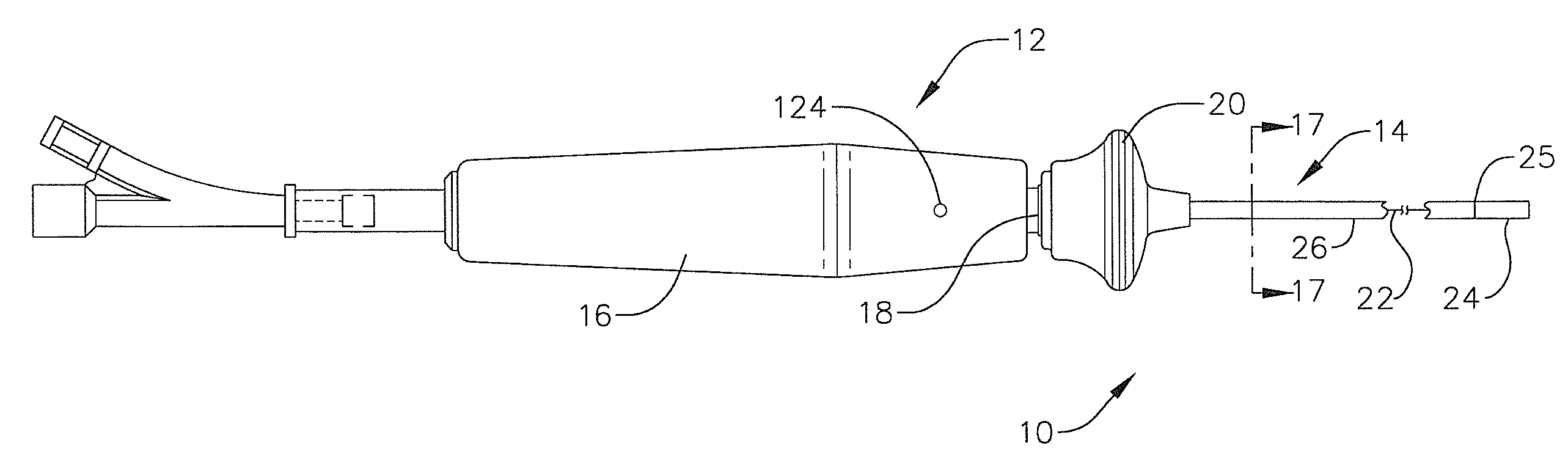
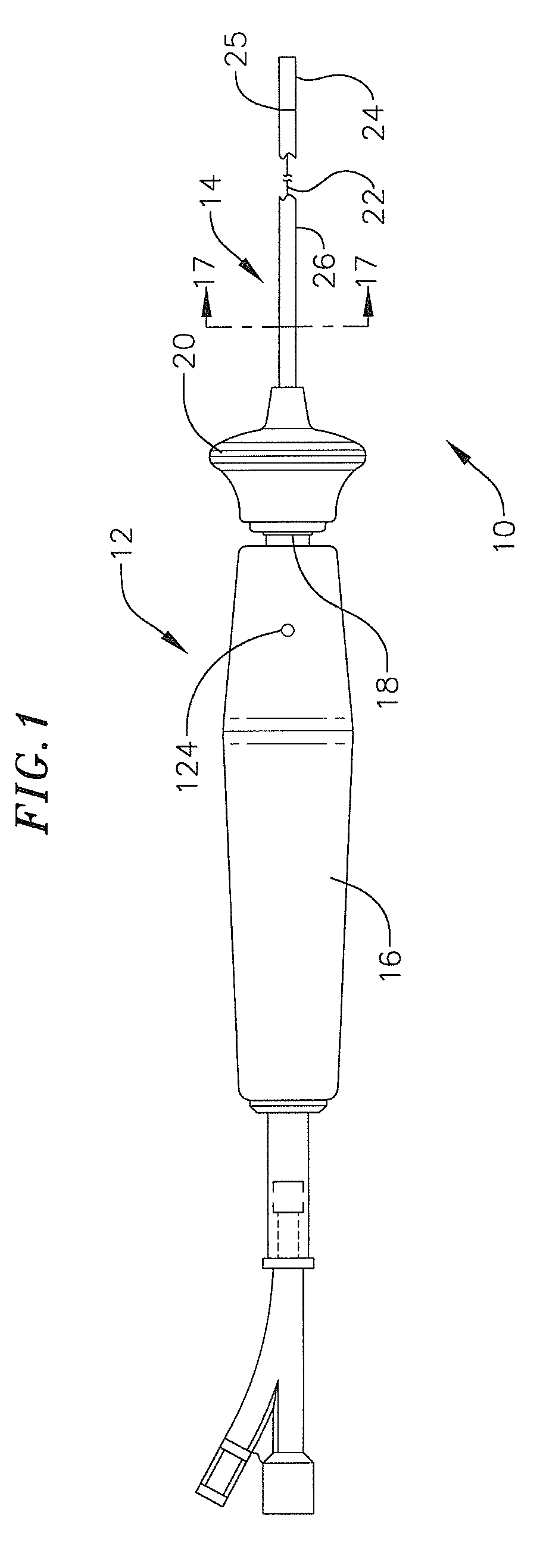
[0053]II. Elongate Body Distal Portion
[0054]III. Elongate Body Proximal Portion
[0055]IV. Handle
The section titles and overall organization of the present detailed description are for the purpose of convenience only and are not intended to limit the present inventions.
I. Overview
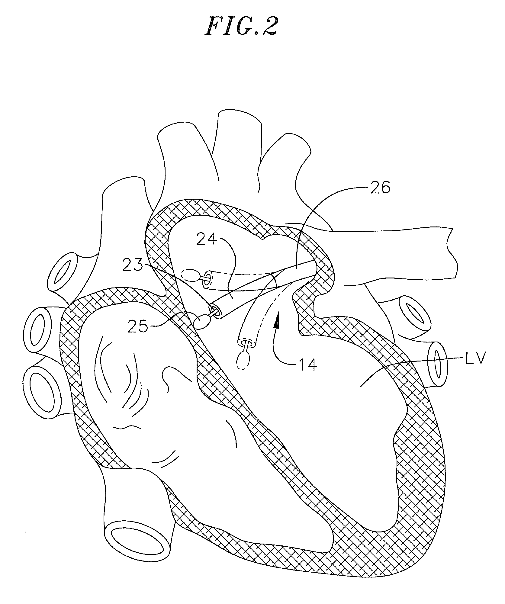
[0056]The present inventions may be used within body lumens, chambers or cavities for diagnostic or therapeutic purposes in those instance where access to interior bodily regions is obtained through, for example, the vascular system or alimentary canal and without complex invasive surgical procedures. For example, the inventions herein have application i...
PUM
 Abstract
Description
Claims
Application Information