Non-pneumatic tire

a non-pneumatic tire technology, applied in the direction of wheels, non-inflatable tyres, vehicle components, etc., can solve the problems of poor shock absorption characteristics, difficult expansion and deformation, and conventional non-pneumatic tires have not been used in passenger vehicles, so as to improve the rigidity of the cylindrical outer member, prevent the spoke structure from buckling, and reduce the weight of the spoke structure

Inactive Publication Date: 2008-03-06
THE YOKOHAMA RUBBER CO LTD
View PDF12 Cites 62 Cited by
  • Summary
  • Abstract
  • Description
  • Claims
  • Application Information

AI Technical Summary

Benefits of technology

[0006]A main object of the present invention is to provide a non-pneumatic tire which includes a spoke structure, which can be easily mounted on a rim of a wheel.
[0007]Another object of the present invention is to provide a non-pneumatic tire whose durability is improved by suppressing the buckling of a spoke structure.
[0009]In the non-pneumatic tire of the present invention, the spoke structure is divided in the tire circumferential direction into the circumferential-direction separate structures. Accordingly, when the spoke structure is to be mounted on a rim of a wheel, it is only necessary to mount these circumferential-direction separate structures one by one on the rim. As a result, the mounting of the spoke structure on a rim of a wheel is facilitated.
[0013]As described above, the spoke structure is further divided in the tire width direction into the three width-direction separate structures while the fins of one of each adjacent two of the width-direction separate structures are displaced in the circumferential direction relative to the fins of the other one. In this case, the fins thus displaced relative to each other operate to enhance the rigidities of the cylindrical outer member between corresponding two of the fins of the adjacent width-direction separate structure. Accordingly, the variation in the rigidity, in the tire circumferential direction, of the cylindrical outer member of the spoke structure is reduced. For this reason, even when the weight of the spoke structure is reduced by reducing the total number of the fins, it is possible to prevent the spoke structure from buckling, and to thus improve the durability.

Problems solved by technology

However, since such conventional non-pneumatic tires are heavy, and have poor shock absorbing characteristics, the conventional non-pneumatic tires have not been used for passenger vehicles for which the ride comfort characteristics are important.
However, it is difficult to expand and deform, in the radial direction, the supporting ring structure having a three-dimensional structure formed of the cylindrical outer member and the cylindrical inner member as described above.
Accordingly, the supporting ring structure is difficult to be mounted on, or removed from, a wheel.
For this reason, there are problems that a special machine, such as a torque machine, is required to mount the supporting ring structure on the rim of the wheel, and that the operation of replacing tires is very difficult.
This results in a problem that a buckling is likely to occur in the portion of the cylindrical outer member in the middle region when the non-pneumatic tire is brought into contact with the ground.

Method used


Image

  • Non-pneumatic tire
  • Non-pneumatic tire
  • Non-pneumatic tire

Examples


Embodiment Construction

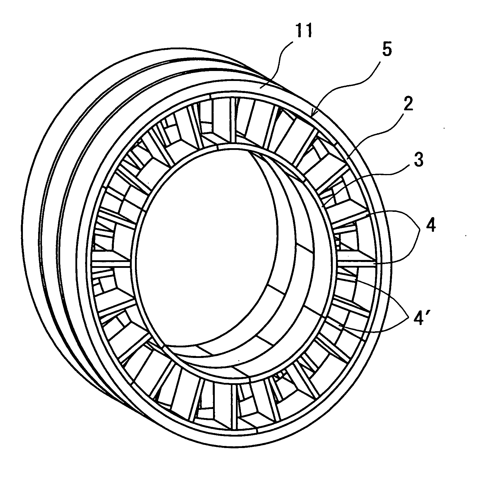
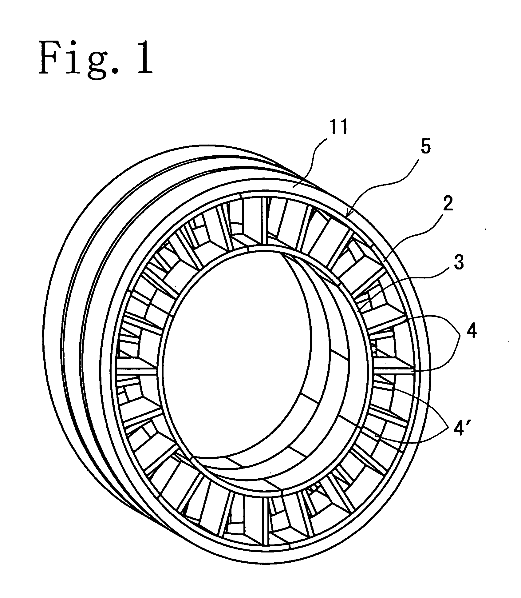
[0018]A non-pneumatic tire of the present invention includes a spoke structure 5 and a tread ring 11 that fits onto the outer periphery of the spoke structure 5, as shown in FIG. 1. The spoke structure 5 includes a cylindrical outer member 2, a cylindrical inner member 3 and a plurality of fins 4 and 4′. The cylindrical outer member 2 and the cylindrical inner member 3 are concentrically arranged, and are connected to each other with the plurality of fins 4 or 4′ arranged in between at intervals in the tire circumferential direction.

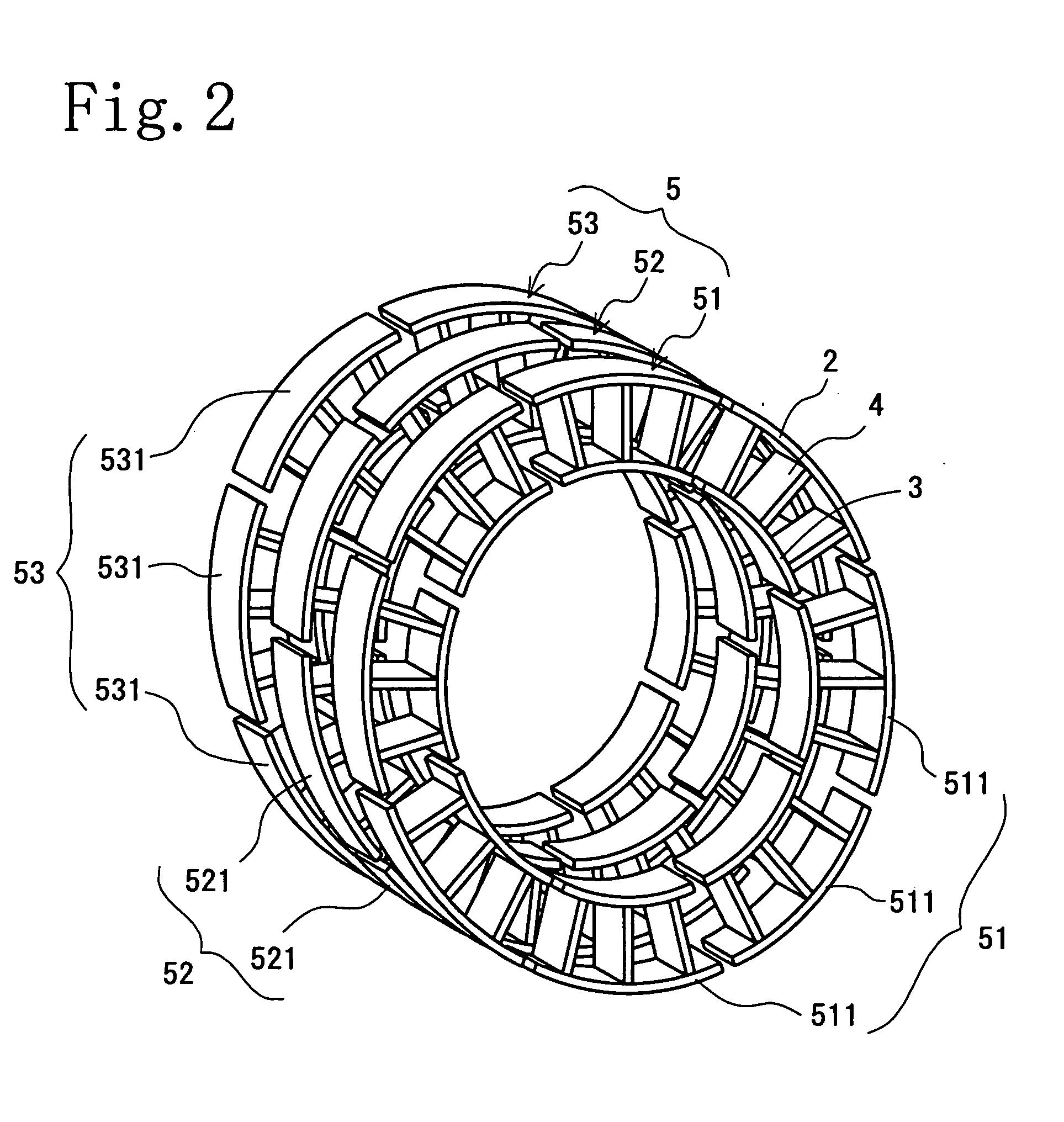
[0019]As shown in FIG. 2, the spoke structure 5 is divided in the tire width direction into three lines so as to be formed of width-direction separate structures 51, 52 and 53. In addition, each of the width-direction separate structures 51, 52 and 53 is divided in the tire circumferential direction into a plurality of pieces so as to be formed of circumferential-direction separate structures 511, 521 or 531. Since the spoke structure 5 is divided in the...


PUM


Abstract

To provide a non-pneumatic tire, including a spoke structure, which can be easily mounted on a rim of a wheel. In addition, to provide a non-pneumatic tire whose durability is improved by suppressing the buckling of a spoke structure.[Solving Means] Provided is a non-pneumatic tire including a spoke structure (5) and a tread ring (11). The spoke structure (5) includes a cylindrical outer member (2) and a cylindrical inner member (3) which are concentrically arranged, and which are connected to each other with a plurality of fins (4, 4′) arranged in between at intervals in the circumferential direction. The tread ring (11) is fitted onto the outer periphery of the spoke structure (5). In the pneumatic tire, the spoke structure (5) is divided in the tire circumferential direction into at least two circumferential-direction separate structures (511, 521, 531).

Description

FIELD OF THE INVENTION[0001]The present invention relates to a non-pneumatic tire, and specifically to a non-pneumatic tire which includes a spoke structure, and which can be easily mounted on a rim.DESCRIPTION OF THE PRIOR ART[0002]Conventionally, non-pneumatic tires including solid tires and cushion tires, each having a solid rubber structure, have been used generally for industrial vehicles. However, since such conventional non-pneumatic tires are heavy, and have poor shock absorbing characteristics, the conventional non-pneumatic tires have not been used for passenger vehicles for which the ride comfort characteristics are important.[0003]A non-pneumatic tire with improved ride comfort characteristics can also be used for passenger vehicles. Patent Document 1 discloses an example of such a tire. In this non-pneumatic tire, an annular tread member is attached to the outer side of a supporting ring structure. The supporting ring structure includes a cylindrical outer member, a cyl...

Claims


Application Information

Patent Timeline
Patent Type & Authority Applications(United States)
IPC IPC(8): B60C7/00
CPCB60C7/08Y10T152/10378B60C7/143B60C7/102
Inventor HANADA, RYOJISETO, HIDEKIHASHIMURA, YOSHIAKIMATSUDA, JUNKITAZAKI, TSUYOSHIKURAMOCHI, IZUMIENDO, KENICHIRO
Owner THE YOKOHAMA RUBBER CO LTD
Why Eureka
Try Eureka