Printing plastic containers with digital images

a plastic container and digital image technology, applied in the field of plastic containers with digital images, can solve the problems of difficult to obtain proper registration between colors, expensive and time-consuming, and conventional printing techniques on curved plastic containers are subject to significant drawbacks

Active Publication Date: 2006-07-06
PLASTIPAK PACKAGING
View PDF5 Cites 85 Cited by
  • Summary
  • Abstract
  • Description
  • Claims
  • Application Information

AI Technical Summary

Benefits of technology

[0007] In accordance with the present invention a series of plastic containers are firmly held and moved to and from a first digital printing location and a first digital image is printed thereon at the first printing location on a first printing area on the containers, with the containers held at the top thereof and at a second position spaced from the top thereof, preferably at the base. Desirably, the containers are moved from the first digital printing location to a second digital printing location and a second digital image printed thereon on a second printing area on the containers spaced from the first printing area, with the containers held at the top thereof and at a second area spaced from the top, preferably at the base. The containers are preferably maintained under internal pressure while the digital image or images are printed thereon.
[0008] The steps of digitally printing the digital image directly onto the plastic container prints the digital images directly onto a preformed container, for example onto an injection molded or blow molded container, such as polyethylene terephthalate (PET) or high density polyethylene (HDPE). The digital printing operation may print the digital image directly onto the plastic container as by jetting ink through an inkjet print head and onto the container surface. The ink may be a UV-reactive ink, in which case after printing the ink may be cured by exposure to UV light. One may also, for example, treat the container surface to be printed prior to the printing operation, as by flame treatment, corona treatment or plasma jet treatment.

Problems solved by technology

Conventional techniques for printing onto curved plastic containers are subject to significant drawbacks.
For example, it is difficult to obtain proper registration between colors, and changing images, designs or wording is expensive and time consuming.
However, it is difficult to satisfactorily use multiple nozzles on curved surfaces.

Method used


Image

  • Printing plastic containers with digital images
  • Printing plastic containers with digital images
  • Printing plastic containers with digital images

Examples


Embodiment Construction

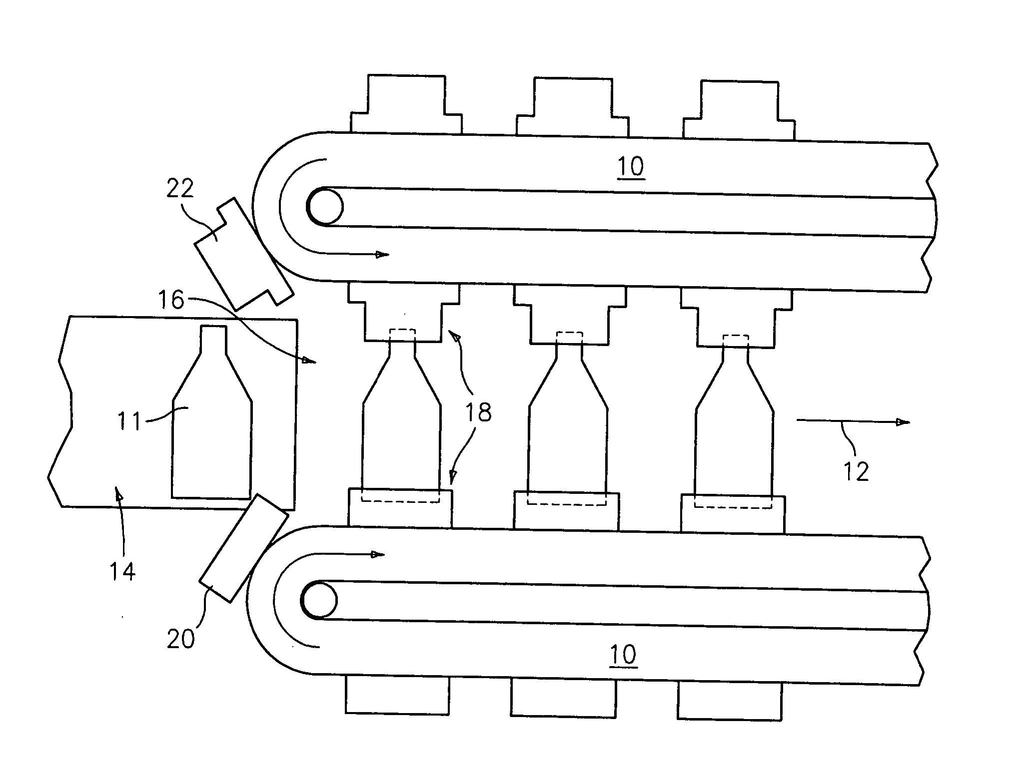
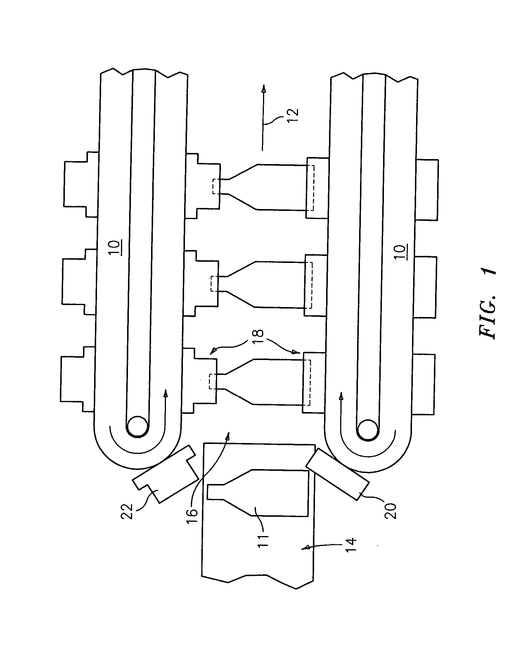
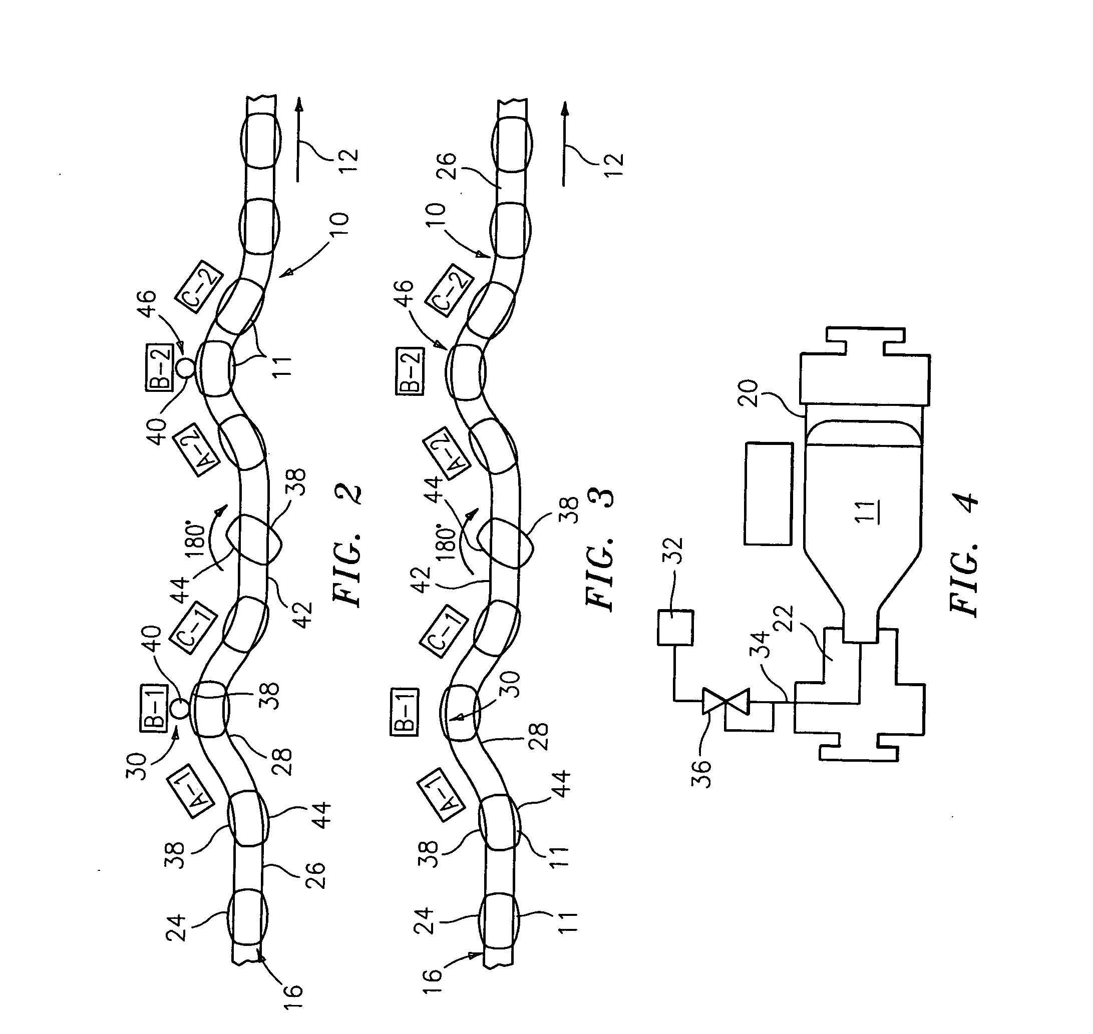
[0016] As can be seen from FIGS. 1-3, a conveyer assembly 10 is provided to move the containers 11 through the treatment procedure in the direction of flow 12. The containers 11 enter the conveyer assembly from infeed conveyer 14 at container entry 16 and are secured in container clamp assembly 18. The clamp assembly secures the containers 11 at two spaced areas, as shown in FIGS. 1 and 4, by container base holder 20 and container top holder 22. It is preferred to hold the container at the top and bottom, although one could employ a top holder plus a second holder spaced therefrom, as on the sidewall. This prevents the containers from moving in any direction except for the direction of container flow 12. The base holder 20 and top holder 22 are synchronized to maintain the same velocity and relationship to each other at all times. Naturally, a commercial operation may have more than one conveyer assembly line.

[0017] As can be seen, particularly in FIGS. 2 and 3, the containers 11 a...


PUM

PropertyMeasurementUnit
air pressureaaaaaaaaaa
internal pressureaaaaaaaaaa
printing areaaaaaaaaaaa

Abstract

A method for printing digital images on plastic containers having curved surfaces, including providing a series of hollow plastic containers, moving the containers along a track past first and second digital printing locations, and printing first and second digital images on the curved container surfaces while maintaining the container being printed under internal pressure and while firmly holding the container being printed at spaced locations thereon.

Description

CROSS-REFERENCE TO RELATED APPLICATION [0001] This application is based on Provisional Application Ser. No. 60 / 640,605, filed Dec. 30, 2004. BACKGROUND OF THE INVENTION [0002] The present invention relates to plastic containers having digital images printed thereon, particularly curved plastic containers. [0003] Conventional techniques for printing onto curved plastic containers are subject to significant drawbacks. For example, it is difficult to obtain proper registration between colors, and changing images, designs or wording is expensive and time consuming. [0004] Inkjet printing with multiple nozzles is useful for flat surfaces. However, it is difficult to satisfactorily use multiple nozzles on curved surfaces. [0005] It would be highly desirable to print a digitally generated image directly onto a plastic container, particularly a curved plastic container, wherein the printing can be done at a reasonable speed and at a reasonable cost. SUMMARY OF THE INVENTION [0006] The prese...

Claims


Application Information

Patent Timeline
Patent Type & Authority Applications(United States)
IPC IPC(8): B41F17/00
CPCB41J3/4073Y10T428/1352B41M5/0082B41J11/002B41J3/543B65C3/26B41J3/40733B41J11/00214
Inventor UPTERGROVE, RONALD L.
Owner PLASTIPAK PACKAGING
Why Eureka
Try Eureka