Method and apparatus for sub-pixel motion compensation

a motion compensation and subpixel technology, applied in the field of digital video motion compensation, can solve the problems of increasing the complexity of the motion compensation implementation, the real bandwidth penalty of the hierarchical approach, and the inability to use just bilinear interpolation in the upper interpolation level, so as to reduce the total amount of math, reduce the cost of motion compensation implementation, and reduce the bus bandwidth

Active Publication Date: 2006-07-06
AVAGO TECH INT SALES PTE LTD
View PDF2 Cites 71 Cited by
  • Summary
  • Abstract
  • Description
  • Claims
  • Application Information

AI Technical Summary

Benefits of technology

[0008] The objects, features and advantages of the present invention include providing a method and / or an apparatus for sub-pixel motion compensation that may (i) use less bus bandwidth than conventional motion compensation approaches, (ii) reduce costs for a motion compensation implementation compared with conventional implementations, (iii) provide sharp filtering, (iv) fetch a least possible worst-case number of pixels from external memory, (v) reduce a total amount of math performed to generate interpolated pixel values compared with conventional approaches, (vi) provide sufficient motion compensation performance for future video coding standards (e.g., H.265) and / or (vii) lower silicon costs compared with existing designs.

Problems solved by technology

Research has shown that using more taps and making the taps programmable, rather than fixed, can lead to impressively increased compression at a cost.
A disadvantage of the existing approaches is that by using multiple levels of interpolation and deriving higher-level interpolated positions from lower-level positions, the upper interpolated levels cannot typically use just bilinear interpolation in order to get the level of performance specified for future video standards.
However, when a second or a third interpolation layer technique utilizes more than two taps (for increased prediction accuracy and coding gain) the hierarchical approach has a real bandwidth penalty increasing cost over a direct interpolation approach.

Method used


Image

  • Method and apparatus for sub-pixel motion compensation
  • Method and apparatus for sub-pixel motion compensation
  • Method and apparatus for sub-pixel motion compensation

Examples


Embodiment Construction

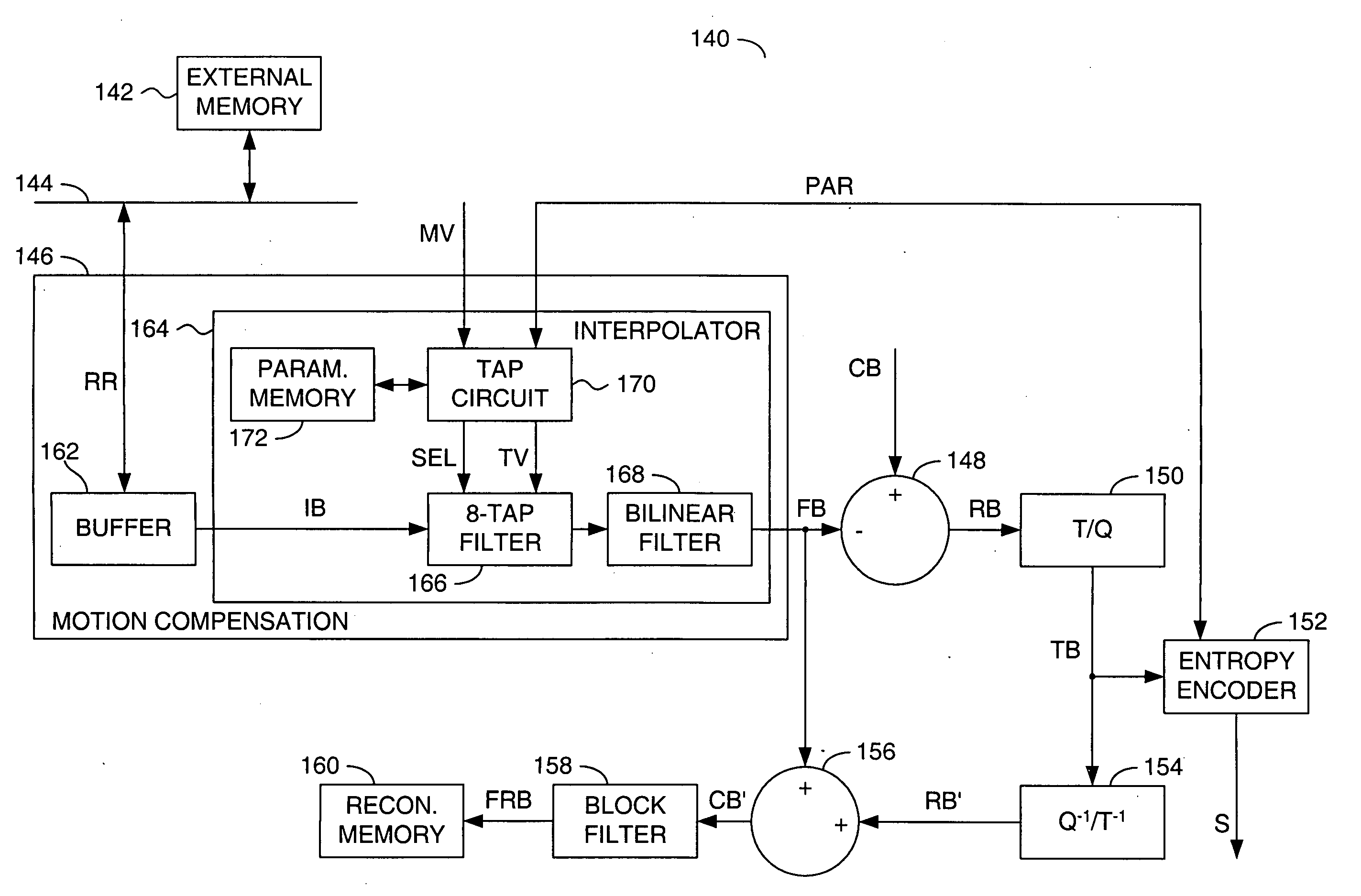
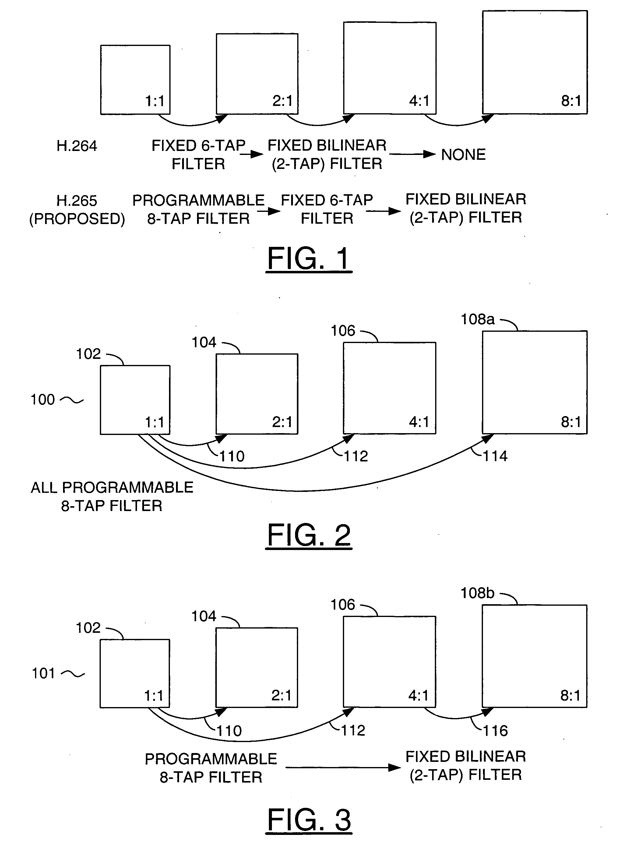
[0019] In the text below, the phrase “direct polyphase interpolation” generally means that successive levels (e.g., half-pel, quarter-pel, eighth-pel, etc.) in order from a lowest level (e.g., half-pel) to a highest level (e.g., eighth-pel) of interpolated pixel values may be derived directly from full-pel data without using lower level data that derived from full-pel data (that may potentially have been clipped prior to being so used). In contrast the phrase “hierarchical interpolation” is generally taken to mean that successive levels are use derived lower level (and potentially clipped) interpolated values as input.

[0020] The present invention generally concerns direct motion compensation structures and / or methods using direct polyphase interpolation. In particular, multiphase (e.g., 8-tap) filters (or interpolators) may implement direct interpolation of all subpel positions from original (e.g., integer) pixel positions using different tap values for the different subpel positio...


PUM


Abstract

A method of motion compensation for an input block is disclosed. The method generally includes the steps of (A) generating a plurality of tap values in response to a motion vector for the input block, (B) generating an interpolated block by programmable filtering a reference block using the tap values, the interpolated block being spatially offset from the reference block by less than a half-pel separation and (C) generating an output block in response to the input block and the interpolated block.

Description

[0001] This application claims the benefit of U.S. Provisional Application No. 60 / 642,140, filed Jan. 5, 2005, which is hereby incorporated by reference in its entirety.FIELD OF THE INVENTION [0002] The present invention relates to digital video motion compensation generally and, more particularly, to a method and apparatus for sub-pixel motion compensation. BACKGROUND OF THE INVENTION [0003] Motion compensation is a major source of coding gain where most of the compression comes from for video. Current motion compensation approaches in existing standards use short-tap fixed interpolation filters. Conventional encoder and decoder techniques are well known and of reasonable cost for the current approaches. Research has shown that using more taps and making the taps programmable, rather than fixed, can lead to impressively increased compression at a cost. Future international compression standards will likely use such techniques, despite the increased cost, to achieve sufficient compr...

Claims


Application Information

Patent Timeline
Patent Type & Authority Applications(United States)
IPC IPC(8): H04N11/04H04N7/12H04B1/66H04N11/02
CPCH04N19/80H04N19/523H04N19/43
Inventor WINGER, LOWELL L.
Owner AVAGO TECH INT SALES PTE LTD
Why Eureka
Try Eureka