Nuclear reactor and means for inserting neutron-absorbing liquid into the core

a technology of neutron absorber and core, which is applied in the direction of nuclear energy generation, climate sustainability, nuclear reaction control, etc., can solve the problems of cumbersome chemical or mechanical complementary means, large volume of installation required for controlling and regulating the operation of the reactor's core, etc., and achieves the effect of fast injection of neutron absorbers, convenient storage and convenient us

Inactive Publication Date: 2006-07-06
EMIN MICHEL
View PDF13 Cites 9 Cited by
  • Summary
  • Abstract
  • Description
  • Claims
  • Application Information

AI Technical Summary

Benefits of technology

[0032] By placing several capillary tubes in parallel, very fast injection of the neutron absorber is obtained. With this particular arrangement, it is possible to achieve an emergency stop system compatible with the requirements for a nuclear reactor.
[0033] Another embodiment consists in completing this assembly with the bell, the purpose of which is to vary the neutron spectrum. This bell may be positioned around an external tube and its capillary tubes. Advantageously, with this last embodiment, it is possible to achieve a variation of the neutron spectrum in the core of the reactor by filling and emptying at will, this open bell on the fluid of the reactor by means of gas transported by the conduits of the internals. By varying the neutron spectrum it is also possible to change nuclei of certain irradiated radioactive materials, such as long-lived waste in order to make them more usable and more storable.

Problems solved by technology

So it is seen that the installation required for controlling and regulating operation of the reactor's core requires a large volume by virtue of the use of control rods, either above or below the core and passing through the vessel, and mobilizes cumbersome chemical or mechanical complementary means.

Method used


Image

  • Nuclear reactor and means for inserting neutron-absorbing liquid into the core
  • Nuclear reactor and means for inserting neutron-absorbing liquid into the core
  • Nuclear reactor and means for inserting neutron-absorbing liquid into the core

Examples


Embodiment Construction

[0064]FIG. 5A is a block diagram of the operation of the reactor according to the invention in the case when the means for inserting a neutron absorber are means for injecting and distributing a neutron-absorbing liquid, and applied to the assembly of fuel pencils.

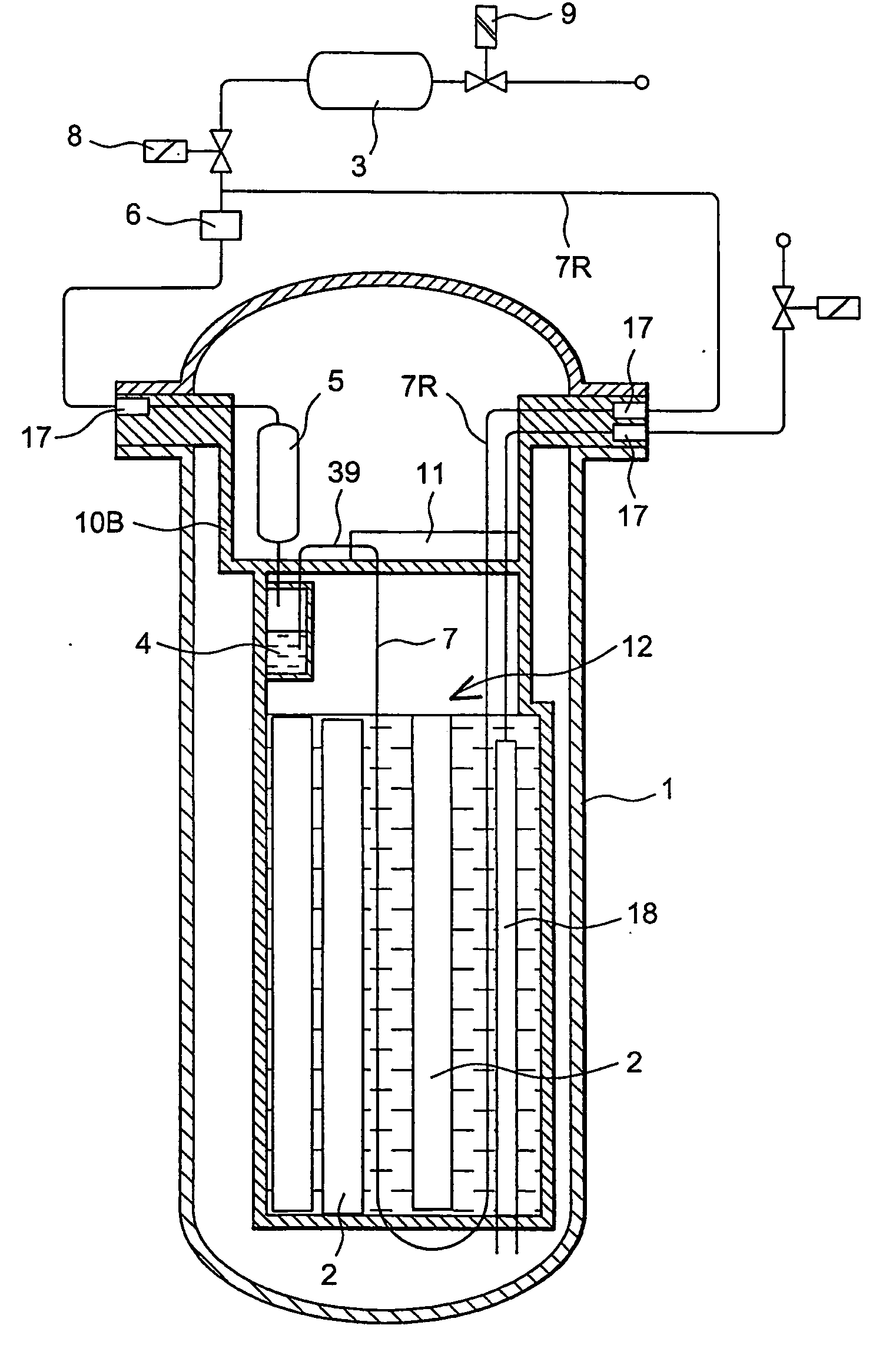
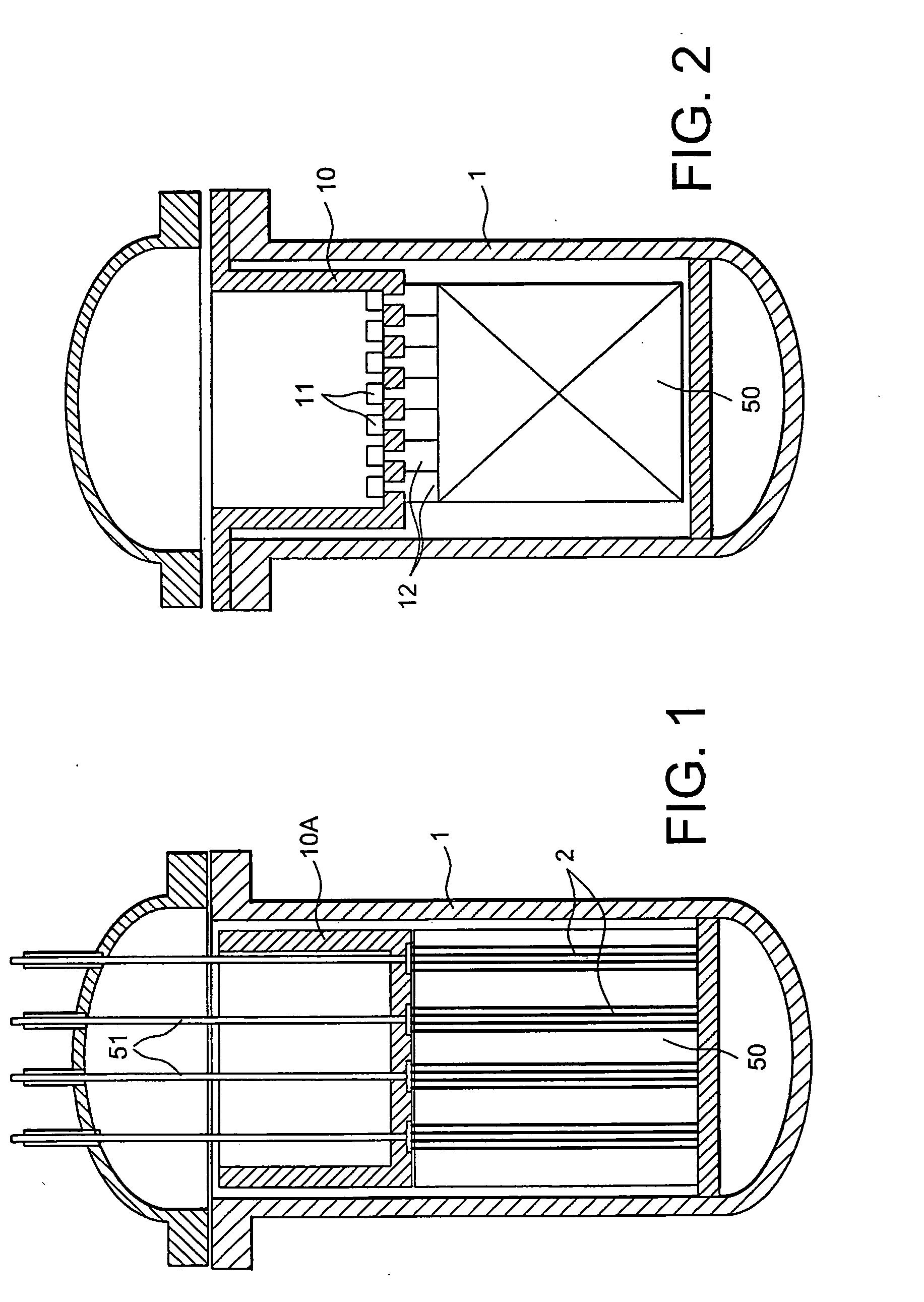
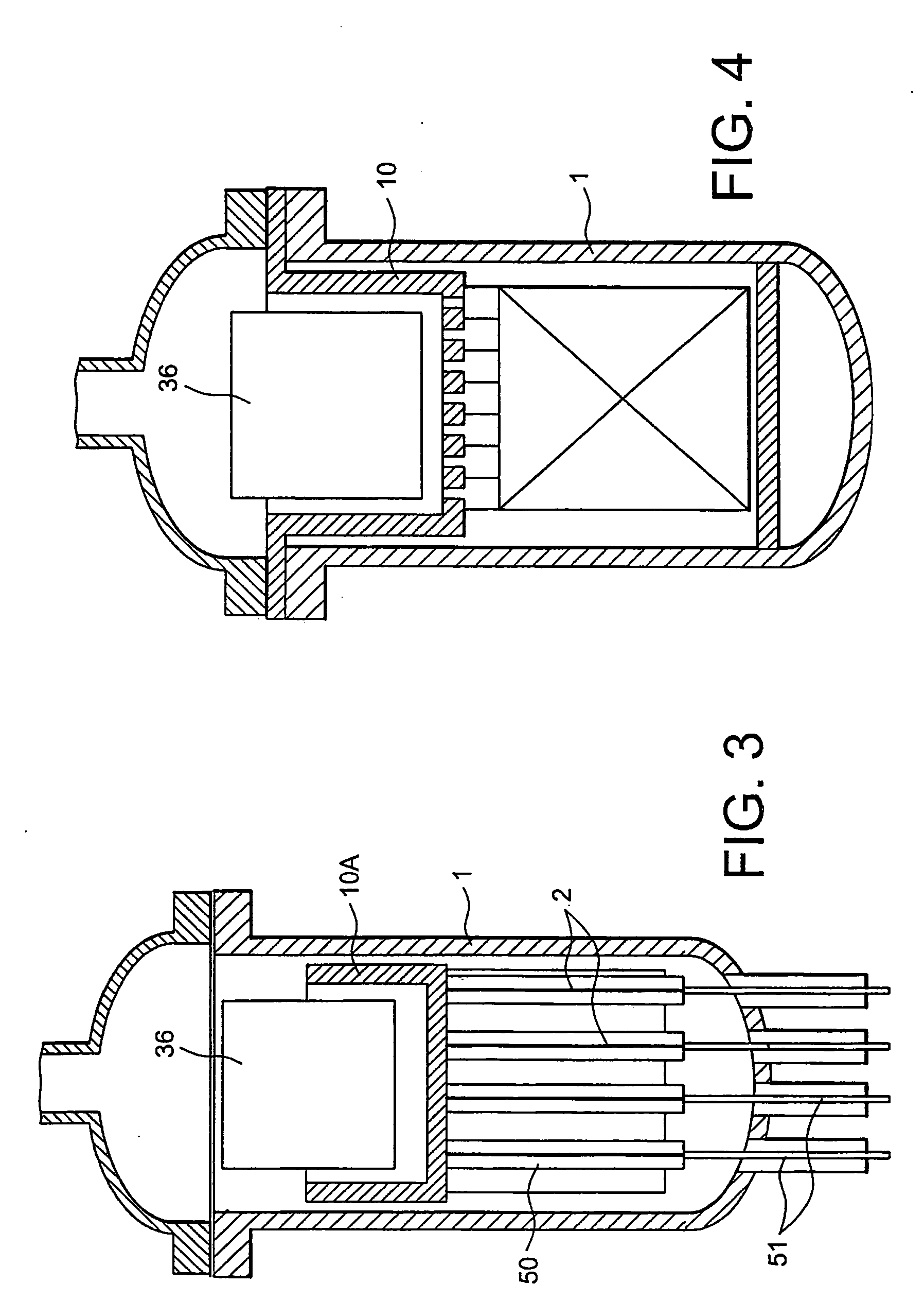
[0065] A nuclear reactor vessel 1 containing a core 50 itself comprising a large series of fuel rods 2, is illustrated schematically. Control of the reactivity in the core 50 is obtained with a neutron-absorbing liquid injected into channels 7 permanently positioned between the fuel pencils 2 by injection channels 7. Above the core 50, one or more tanks of neutron-absorbing liquid 4 are found from which emerge injection channels 7. The whole is placed under the internal part 10 (or the internal assembly if it is made in several portions) which is used in each nuclear reactor to hold the core 50 into place, i.e., in the lower portion of the vessel 1.

[0066] This FIG. 5A highlights a portion of the transmission means, i.e.,...


PUM


Abstract

Installations for mounting, controlling, and guiding control rods in and outside a vessel may be removed and passage through an upper internal part may thereby be avoided. An upper internal part is placed near the core of a reactor and laterally emerges on the outside of the vessel. All the transmission, control, and fluid systems pass through this internal part and emerge, by a mobile connection part, for each cluster of control rods, on an assembly head containing tanks of liquid neutron absorber, and injection circuits in injection channels placed between the fuel rods.

Description

FIELD OF THE INVENTION [0001] The invention relates to nuclear reactors, and in particular to means for inserting a neutron absorber, such as a neutron-absorbing liquid, when the latter is used, for controlling and modulating the instantaneous power of a nuclear reactor. More specifically, with it, it is possible to ensure emergency stopping of the latter, to modulate the flux of neutrons applied for modulating the nuclear power without any significant deformation of the core, to regenerate the operating nuclear fuel, and then to use this regenerated fuel without unloading the latter. [0002] The invention is applied to all types of nuclear reactors, whether they are reactors with pressurized water, with boiling water, with gas coolant, with molten metals, or even with heavy water. PRIOR ART AND THE POSED PROBLEM [0003]FIG. 1 shows in a vertical sectional view, a first type of nuclear reactor of the pressurized water type from the prior art. Reference 1 designates, as in the other fi...

Claims


Application Information

Patent Timeline
Patent Type & Authority Applications(United States)
IPC IPC(8): G21C7/00G21C7/16G21C7/22
CPCG21C7/16G21C7/22G21Y2002/301G21Y2002/302G21Y2002/304G21Y2002/402G21Y2002/50G21Y2004/30G21Y2004/40Y02E30/39Y02E30/30
Inventor EMIN, MICHEL
Owner EMIN MICHEL
Why Eureka
Try Eureka