Sanitary hub assembly and method for impeller mounting on shaft

Active Publication Date: 2006-07-06
SPX FLOW INC
View PDF14 Cites 15 Cited by
  • Summary
  • Abstract
  • Description
  • Claims
  • Application Information

AI Technical Summary

Benefits of technology

[0007] The foregoing needs are met, to a great extent, by the present invention, wherein in one aspect of an apparatus and method is provided that in some embodiments can

Problems solved by technology

Some known disassemblable hub mounting arrangements can present the problem that during operation the material comes in contact with complex

Method used


Image

  • Sanitary hub assembly and method for impeller mounting on shaft
  • Sanitary hub assembly and method for impeller mounting on shaft
  • Sanitary hub assembly and method for impeller mounting on shaft

Examples


Example

[0019] The foregoing needs are met, to a great extent, by the present invention, wherein in one aspect an apparatus and method is provided that in some embodiments can be easily mounted onto a shaft at the desired axial location, and adjusted to a different axial location and / or removed entirely when desired, and which is easy to clean.

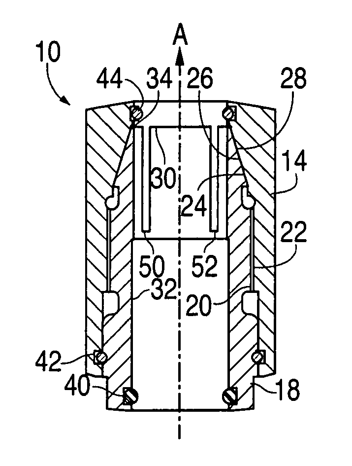
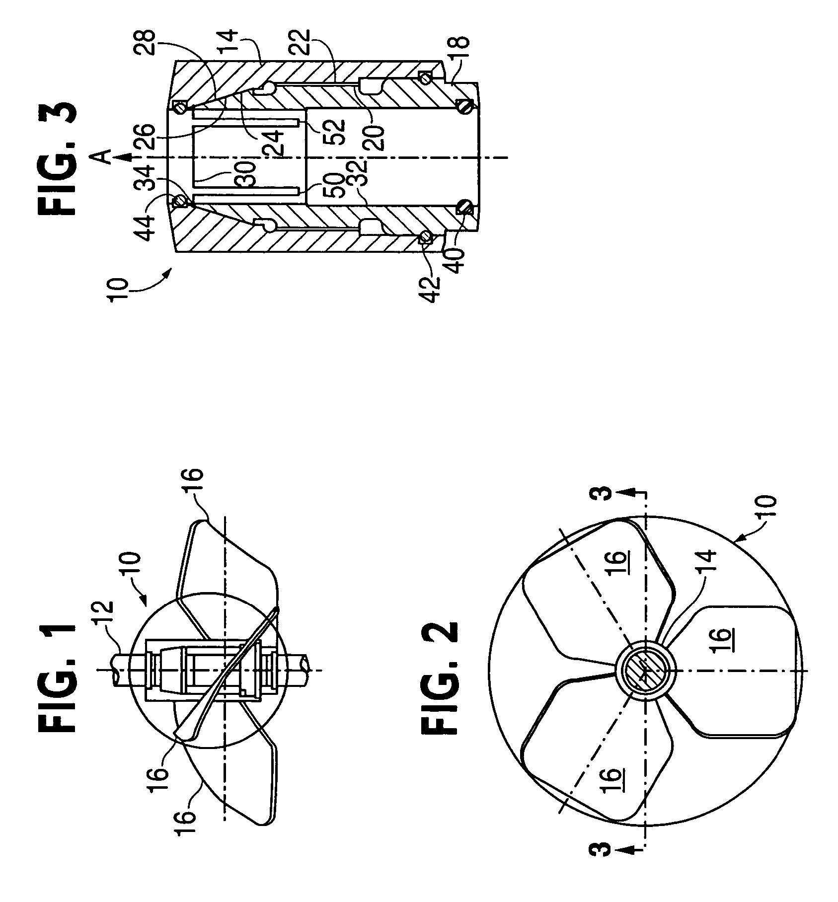
[0020] Some preferred embodiments of the invention will now be described with reference to the drawing figures, in which like reference numerals refer to like parts throughout. Turning to FIG. 1, a side view of an impeller hub and blade assembly 10 mounted on to a shaft 12 is depicted.

[0021]FIG. 2 is a top view of the impeller hub and blade assembly 10 of FIG. 1 showing the impeller hub and blade assembly 10 being mounted on the shaft 12 and having an outer impeller hub 14 from which radially extend three impeller blades 16. The impeller blades 16 shown are exemplary and it is to be understood that any of a wide variety of impeller blades lengths an...


PUM


Abstract

A hub for removable mounting onto a shaft has an inner sleeve having a first end and a second end, and having a substantially cylindrical inner diameter and having an outer surface having a threaded region and a tapered conical surface located substantially near the first end. An outer hub has an inner surface with a threaded region threadably engagable with the threaded region of the inner hub, and a inner tapered conical surface configured to cam along the tapered outer surface of the inner hub. The hub can be locked at a desired axial location or the shaft by engaging the threads to cause the cam surfaces to constrict the diameter of the first end so it frictionally locks onto the shaft.

Description

FIELD OF THE INVENTION [0001] The present invention relates generally to the field of hubs that are mounted onto a rotating shaft, for example, hubs that support impellers that are mounted to a rotating mixer shaft. More particularly, the present invention relates to hubs that are removably mounted onto a mixer shaft. BACKGROUND OF THE INVENTION [0002] Mixing devices are in wide use in industry, and many mixing devices typically include a vessel, which contains a liquid or other material to be mixed, and an impeller shaft running through some or all of a length inside the vessel. The impeller shaft is typically rotatibly driven by a motor, often located at the top of the vessel. There are radially extending impellers, which are mounted to the shaft at one or several axial locations on the length of the shaft and are in the form of paddles or blade type features that extend radially outward from the shaft. The impellers mix and or otherwise impart energy to the material inside of the...

Claims


Application Information

Patent Timeline
IPC IPC(8): F16D33/00
CPCF16D1/096Y10T403/52Y10T403/7069Y10T403/68F16B2200/60
Inventor HU, XIAOBINGKOCIENSKI, ANTHONY C.
Owner SPX FLOW INC
Why Eureka
Try Eureka