
Water guiding mechanism of teeth cleaning machine

a technology of teeth cleaning machine and water guiding mechanism, which is applied in the field of water guiding mechanism of teeth cleaning machine, can solve the problems of teeth damage, dentists and patients being subjected to tremendous persecution, and achieve the effect of strong pressur

Inactive Publication Date: 2006-07-06
TSAI CHIH I
View PDF6 Cites 10 Cited by
  • Summary
  • Abstract
  • Description
  • Claims
  • Application Information

AI Technical Summary

Benefits of technology

[0012] It is therefore a primary object of the invention to provide a water guiding mechanism of teeth cleaning machine that minimizes the possibility to spray water on patients' faces, and can be sterilized by high temperature and high pressure to reduce cross-infection among patients.

Problems solved by technology

However, referring to FIG. 5 and FIG. 6, cooling water flows out from the stainless water pipe d1, the swing of the stainless water pipe d1 makes the water outlet d10 deviate away from the center of the bend c10, the water sprayed out from the water outlet d10 cannot flow to the stainless tip c11, such might cause teeth damage by the overheating of the stainless tip c11; the gap between the stainless water pipe d1 and the metal base b1 might have germs and bacteria; the stainless material of the stainless water pipe d1 is not easy to tear off for cleaning and disinfection, that might potentially spread disease.
However, the front end water path c32 of the third type teeth cleaner is installed inside the stainless-steel head c3, the front end water path c32 is drilled out inside the stainless-steel head c3, the strength of the stainless-steel head c3 is not so strong, the stainless-steel head c3 might break by the strike of the high speed vibration, the broken stainless-steel head c3 might enter patients' body during cleaning, such will cause dentists and patients tremendous persecution.

Method used


Image

  • Water guiding mechanism of teeth cleaning machine
  • Water guiding mechanism of teeth cleaning machine
  • Water guiding mechanism of teeth cleaning machine

Examples


Embodiment Construction

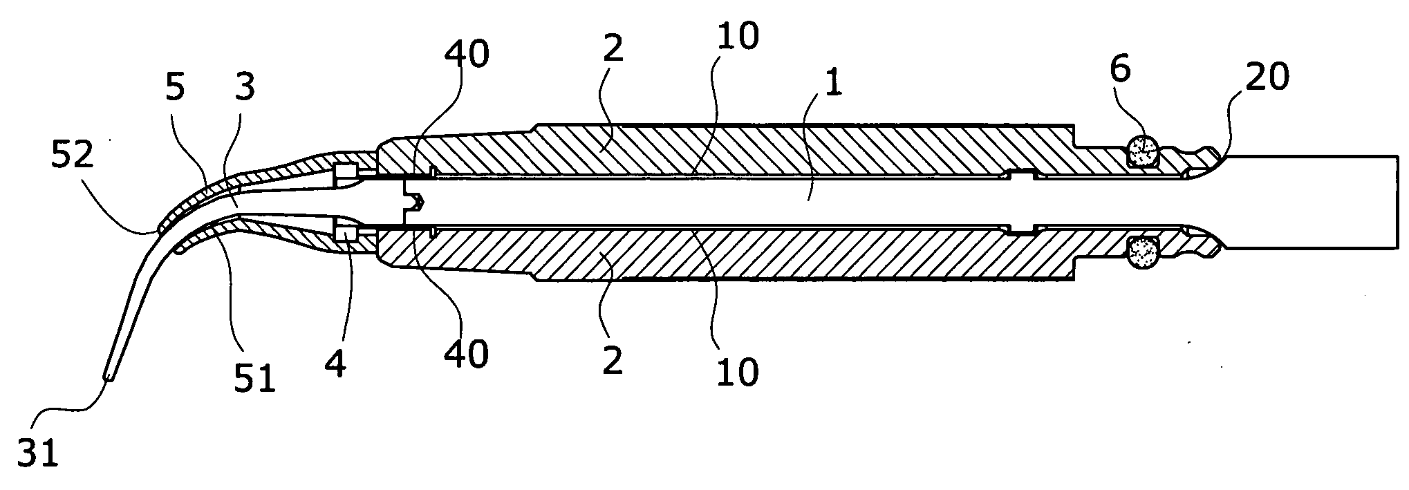
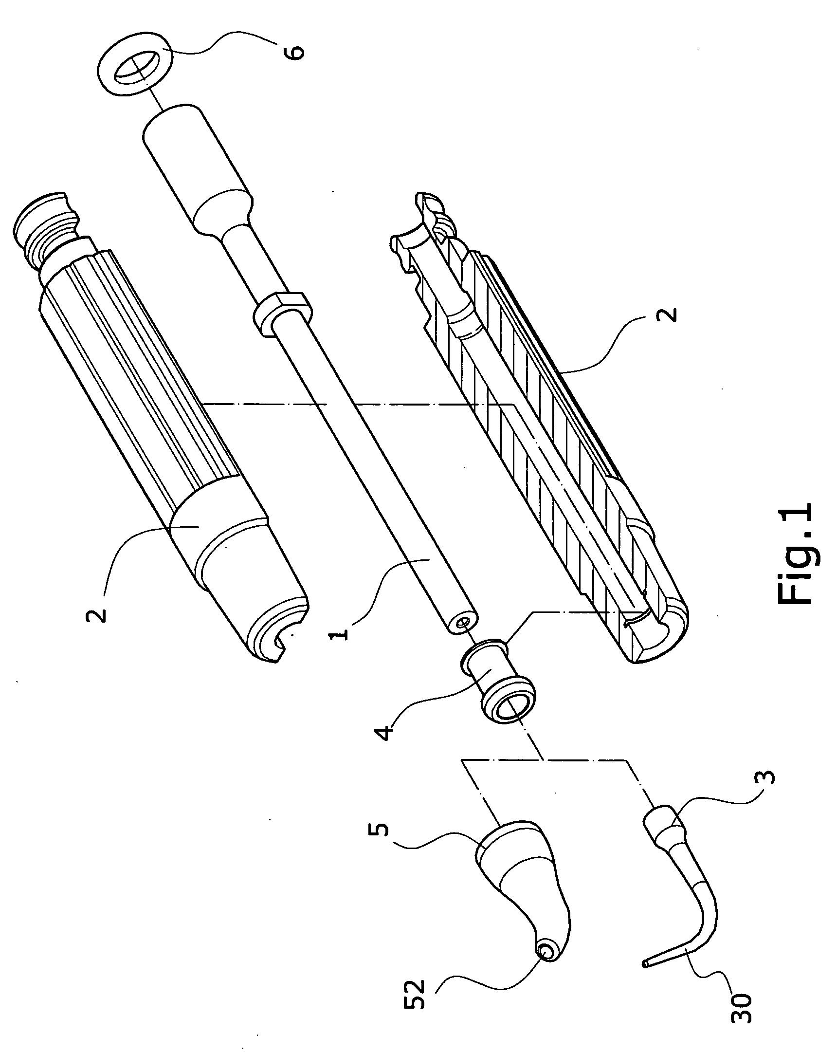
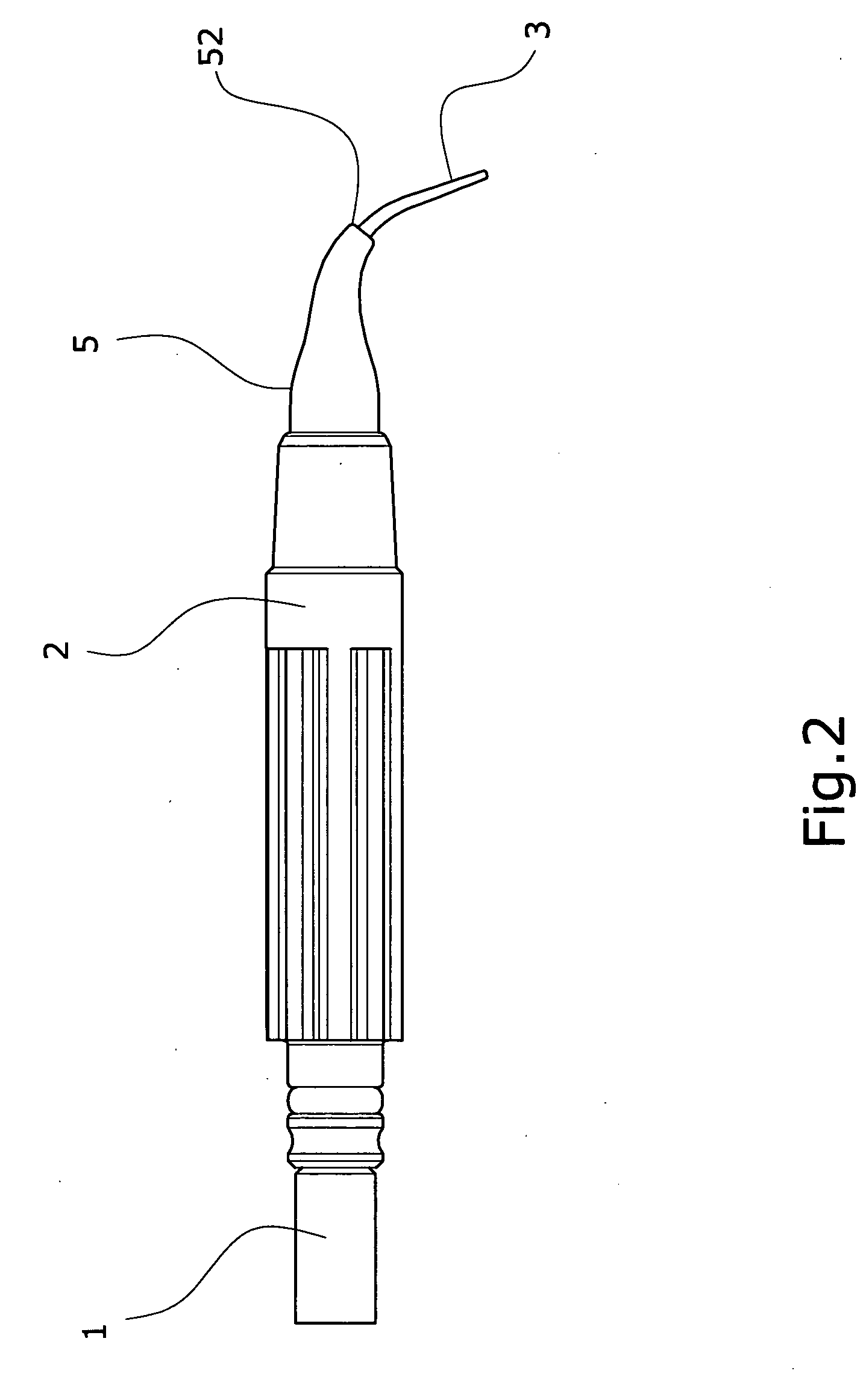
[0024] Referring to FIG. 1 to FIG. 4, the present invention comprises a center shaft 1, a plastic base 2 and an ‘O’ shape ring 6, a water duct 10 is between the center shaft 1 and the plastic base 2, a water inlet hole 20 is on the back of the plastic base 2. The function of each component is described as following:

[0025] A stainless-steel head 3 is installed on the front of the center shaft 1, a bend 30 is on the center of the stainless-steel head 3, a sleeve 4 in on the front inner side of the plastic base 2, the front of the sleeve 4 stretches out front the plastic base 2 for a certain distance, a water outlet duct 40 is installed among the sleeve 4, the center shaft 1 and the stainless-steel head 3, a silicon sleeve 5 is on the front brink of the sleeve 4.

[0026] The silicon sleeve 5 wraps the backside of the stainless-steel head 3 and around the bend 30, a compression chamber 50 is installed between the back half of the silicon sleeve 5 and the stainless-steel head 3, a flow g...


PUM


Abstract

A water guiding mechanism of teeth cleaning machine comprising a center shaft, a plastic base and an ‘O’ shape ring, the major character as following: a stainless-steel head is installed on the front of the center shaft, a bend is on the center of the stainless-steel head, a sleeve in on the front inner side of the plastic base, a silicon sleeve is on the front brink of the sleeve, the silicon sleeve wraps the backside of the stainless-steel head and around the bend, a compression chamber is installed between the back half of the silicon sleeve and the stainless-steel head; based on the structure described above, the compression chamber of the silicon sleeve is applied to guide and compress water, the stainless tip can aim upward, and achieve the effect to minimize the possibility to have water spray on patients' faces.

Description

BACKGROUND OF THE INVENTION [0001] I. Field of the Invention [0002] This invention relates generally to a water guiding mechanism and, more specifically, to a water guiding mechanism of teeth cleaning machine that tests the high frequency transmission IC's, the present invention achieves lower manufacturing cost, better contact of IC pins and the contact parts of the test connectors to reduce contact impedance, magnetic wave interference for better high frequency transmission effect. [0003] II. Description of the Prior Art [0004] Heretofore, it is known that teeth cleaning can remove tartar, stains and spots of teeth to make the surface of teeth smooth and easy to clean, reduce the possibility of periodontal disease. The regular teeth cleaning machine have a cleaning head, as shown in FIG. 5, the cleaning head consists of a center shaft a1 and a metal base b1, the center shaft a1 is installed inside the metal base b1, a stainless-steel head c1 is on the front of the center shaft a1,...

Claims


Application Information

Patent Timeline
IPC IPC(8): A61C1/10
CPCA61C3/03A61C17/0202A61C1/052A61C17/18
Inventor TSAI, CHIH-I
Owner TSAI CHIH I
Learn More