Blood pressure meter cuff

Inactive Publication Date: 2006-07-06
OMRON HEALTHCARE CO LTD
View PDF8 Cites 11 Cited by
  • Summary
  • Abstract
  • Description
  • Claims
  • Application Information

AI Technical Summary

Benefits of technology

[0020] A width of the fluid bag is a width suitable for pressurizing a radial artery present in the downward vicinity of the body surface and in an intermediate portion between the radial styloid process of a wrist and the first metacarpal bone base thereof. With such a width of a fluid bag adopted, it is possible to pressurize only the radial artery present in the downward vicinity of the s

Problems solved by technology

In actual cases of adopting this kind of cuff, a problem has been a risen to some of users that a pressurization pressure of a fluid bag does not correctly act on a target artery and the target artery is not sufficiently pressurized, therefore disabling a blood pressure to be correctly measured.
In this case, this pulsation is sensed as a change in cuff pressure, leading to a factor for measurement error if a chance allows.
According to observation by the inventors, i

Method used


Image

  • Blood pressure meter cuff
  • Blood pressure meter cuff
  • Blood pressure meter cuff

Examples


embodiment 1

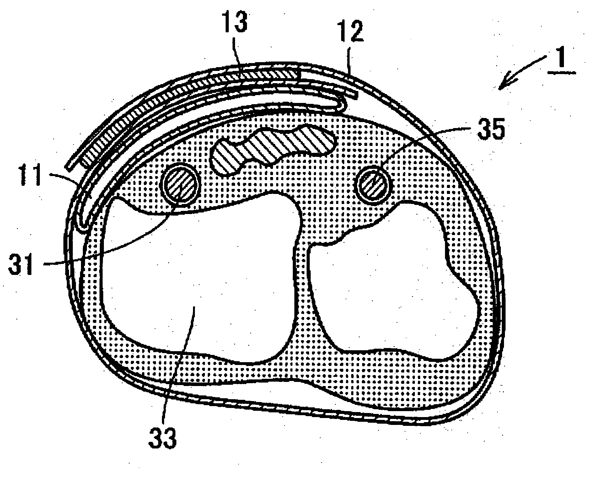
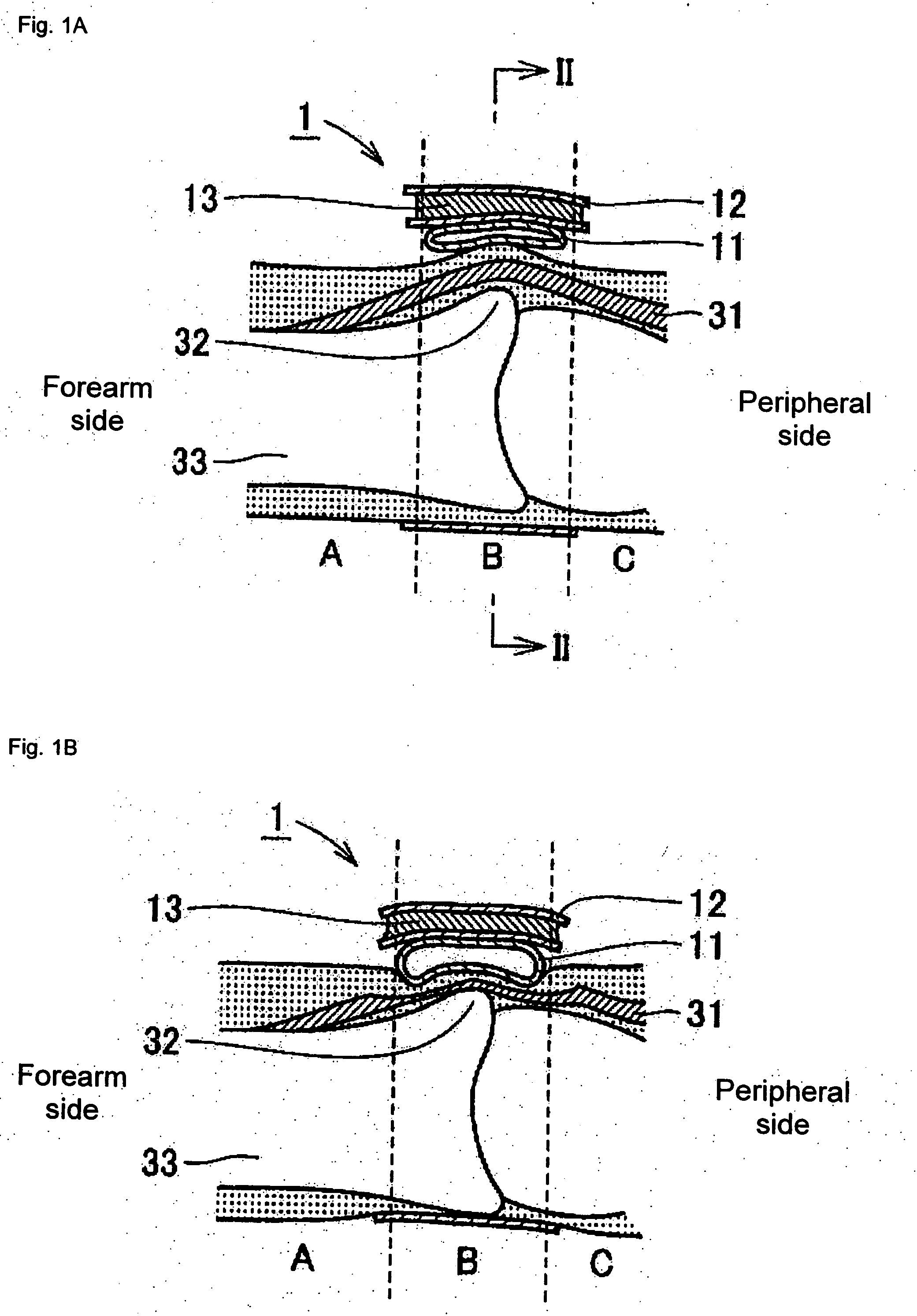
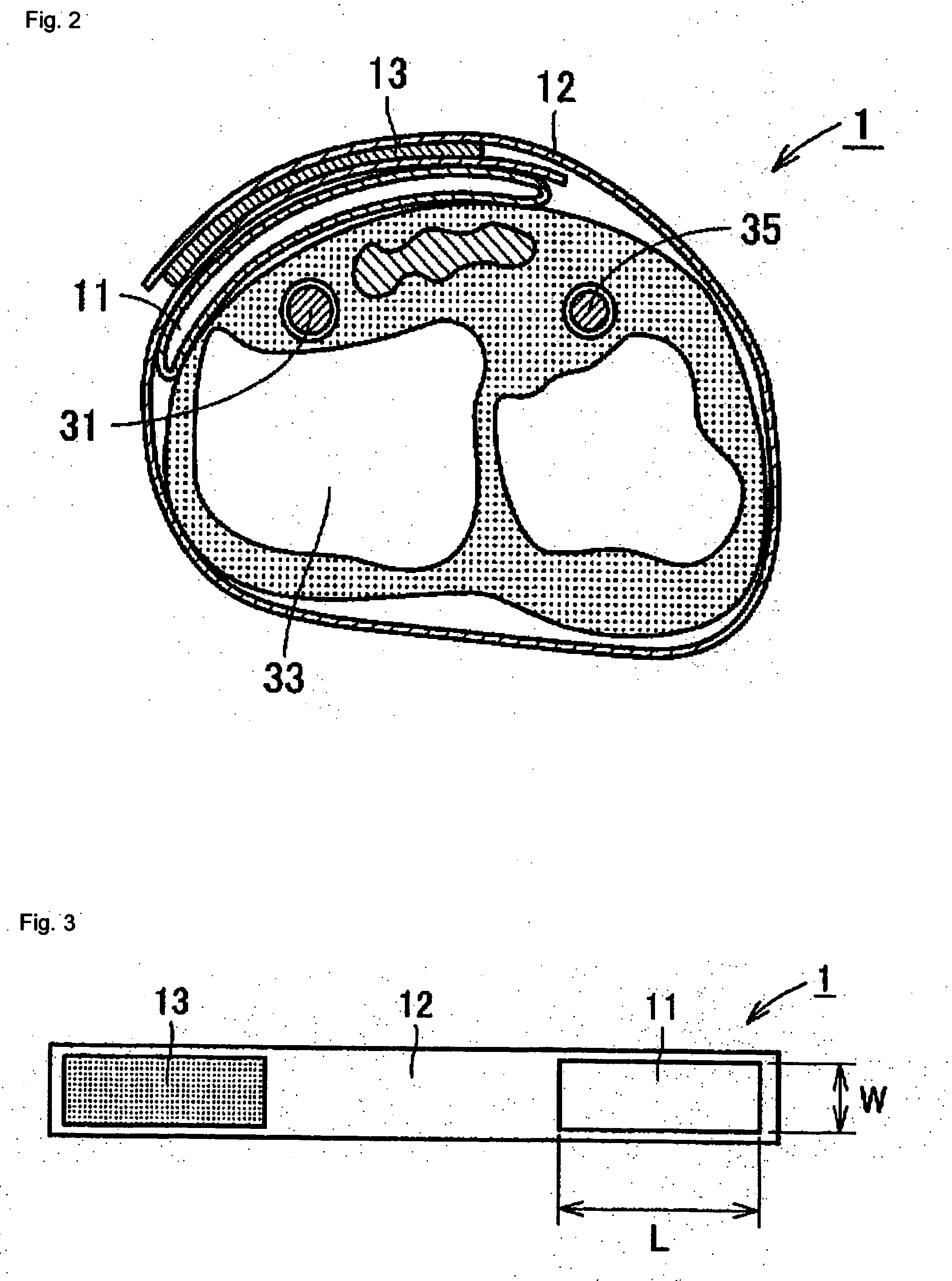
[0028] Description will be given of a blood pressure meter cuff in this embodiment below with reference to FIGS. 1A and 1B to 4A and 4B. FIGS. 1A and 1B are sectional views showing states where a blood pressure meter cuff in this embodiment is mounted on a wrist, FIG. 2 is a sectional view taken on line II to II normal to arrows in FIG. 1A showing a state where the cuff is mounted on a wrist, FIG. 3 is a top plan view of the cuff in a state where the cuff is extended to be flat and FIGS. 4A and 4B are perspective views showing the cuff in a state where the cuff is mounted on a wrist.

(Structure of Blood Pressure Meter Cuff)

[0029] Description will be given of the structure of a blood pressure meter cuff 1 with reference to FIGS. 1A and 1B to 3. The blood pressure meter cuff 1 of this embodiment is used in a wrist blood pressure meter and equipped with a fluid bag 11 into which a fluid such as air is injected and a band 12 as a fixing tool fixing the fluid bag 11 on a wrist.

[0030] ...

embodiment 2

[0038] Description will be given of the second embodiment focusing on only matters different from the above embodiment with reference to FIG. 5. Note that FIG. 5 is a top plan view of a skeleton of a wrist as viewed from the palm side.

[0039] In the above embodiment, the cuff 1 is designed so as to be suitable for pressurizing the radial artery 31 in the downward vicinity of the body surface and above the radial styloid process 32. In this embodiment, the cuff 1 is designed so as to be suitable for pressurizing the radial artery present in the downward vicinity of the body surface in an intermediate portion M between the radial styloid process 32 and the first metacarpal bone base 34 as shown in FIG. 5.

[0040] According to experiments conducted by the inventors, in a case of the radial artery, it has been confirmed that a pulse wave can be sensed most stably at a position spaced to the peripheral side from the top from the top of the radial styloid process 32 by a distance in the ra...


PUM


Abstract

Provide is a blood pressure meter cuff capable of avoiding an influence of an edge effect by pressurizing only a portion of a blood vessel in the downward vicinity of the body surface to thereby measure a correct blood pressure. A blood pressure meter cuff 1 includes: a fluid bag into which a fluid is injected; and a fixing tool fixing the fluid bag on a limb of a human body or the like, wherein a width in the axial direction of the limb, of the fluid bag is a value suitable for selectively pressurizing only a portion of a blood vessel present in the downward vicinity of the skin. In a case where pressurization is imposed on only a portion of the radial artery present in the downward vicinity of the body surface and adjacent to a radial styloid process of a wrist, a width, in the axial direction of a limb, of the fluid bag is set to 15 mm or more and 25 mm or less.

Description

BACKGROUND OF THE INVENTION [0001] 1. Field of the Invention [0002] The present invention relates to a blood pressure meter cuff equipped with a fluid bag into which a fluid is injected and a fixing tool fixing the fluid bag. [0003] 2. Description of the Prior Art [0004] There have been available various kinds of non-invasive blood pressure measuring methods, among which, currently, an oscillometric method (or an oscillation method) is most widely proliferated. The oscillometric method is conducted such that a tourniquet in a belt-like shape called a cuff having a fluid bag therein is fixedly wrapped around a limb and an internal pressure is given to the fluid bag to pressurize an artery in the limb to capture a change in arterial volume determined in a balance between an pressurization pressure as a reaction and a pressure in the artery and estimate a blood pressure value. To be more concrete, since a change in arterial volume is sensed as a change in internal pressure in the fluid...

Claims


Application Information

Patent Timeline
IPC IPC(8): A61B5/02A61B5/022
CPCA61B5/02233
Inventor SHIRASAKI, OSAMUSANO, YOSHIHIKOOHTANI, TOSHIOINOUE, TOMONORI
Owner OMRON HEALTHCARE CO LTD
Why Eureka
Try Eureka