
Printer

a printing machine and printing plate technology, applied in printing, metal working equipment, other printing equipment, etc., can solve the problems of shortening the cutting time, affecting the cutting accuracy, so as to ensure the generation of a driving force suitable for the width and thickness of printed paper, the effect of simple structure and low cos

Inactive Publication Date: 2021-11-25
MITSUBISHI ELECTRIC CORP
View PDF0 Cites 1 Cited by
  • Summary
  • Abstract
  • Description
  • Claims
  • Application Information

AI Technical Summary

Benefits of technology

The present invention is a printer that uses sensors to detect the width and thickness of paper and the position of the movable blade in real-time. Based on these detection results, the printer adjusts its driving force accordingly. This ensures that the printer is suitable for different paper widths without needing many sensors. The printer has a simple structure, is cost-effective, and can improve cutting accuracy and quality. Overall, the present invention provides a printer with improved cutting performance and quality at a reduced cost.

Problems solved by technology

This is because when the printed paper having a large thickness is cut, the driving torque of the movable blade becomes large, so that the printed paper is likely to become unstable due to a shock at the time of cutting and the accuracy of the cutting position is likely to decrease.
Further, in the thermal transfer printer, it is required to shorten the cutting time.

Method used


Image

  • Printer
  • Printer
  • Printer

Examples


Embodiment Construction

)

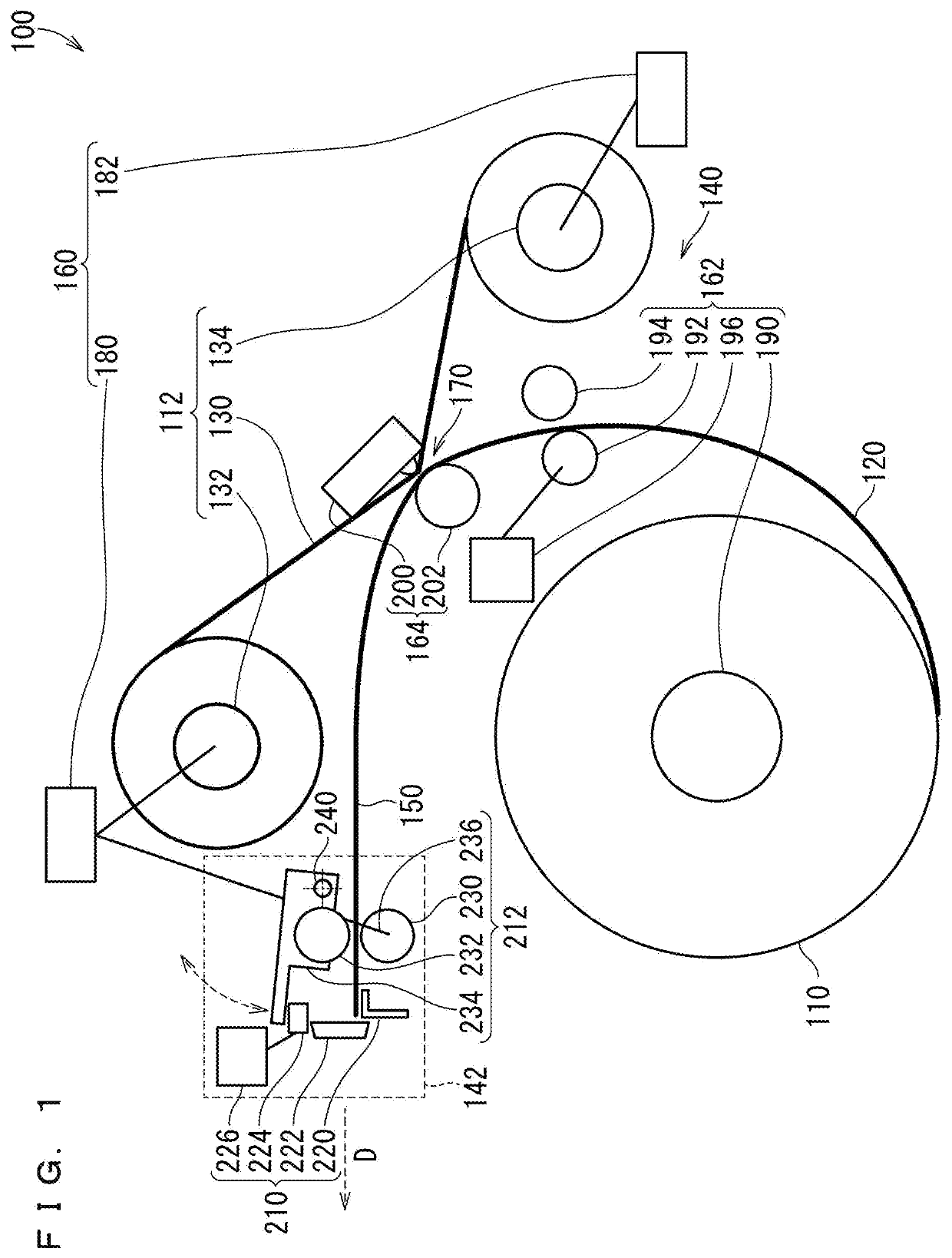
[0041]1 Outline of printer

[0042]FIG. 1 is a side view schematically illustrating a printer of Embodiment 1.

[0043]A printer 100 illustrated in FIG. 1 is a thermal transfer printer.

[0044]A roll of paper 110 and an ink cassette 112 are attached to the printer 100.

[0045]The roll of paper 110 includes paper 120 wound in a roll shape.

[0046]The ink cassette 112 includes an ink sheet 130, an unwinding (SP) side bobbin 132, and a winding (TU) side bobbin 134. The ink sheet 130 includes a sheet-shaped substrate. Yellow (Y), magenta (M), and cyan (C) ink dyes are applied to the sheet-shaped substrate, and an OP material that constitutes an overcoat (OP) that protects the surface to be printed is applied. The combination of Y, M, and C may be replaced with other multiple color combinations. The application of the OP material may be omitted. The ink sheet 130 is wound around the SP side bobbin 132 and the TU side bobbin 134, connecting the SP side bobbin 132 and the TU side bobbin 134.

[0047]The...


PUM


Abstract

Provided is a printer having a simple structure, which is low in cost, and capable of shortening of the cutting time, improving cutting accuracy of the printed paper and improving the quality of an output printed object. A printing mechanism performs printing on paper delivered from a roll of paper by a thermal transfer method and produce printed paper. The movable blade moves in the width direction, and cuts the printed paper. A control unit controls the movable blade drive unit based on the width and the thickness of the paper and the moving distance of the movable blade detected after it is detected that the movable blade is at the standby position, and causes the movable blade drive unit to generate a driving force that changes according to the width, the thickness, and a position of the movable blade in the width direction of the paper.

Description

TECHNICAL FIELD[0001]The present invention relates to a printer.BACKGROUND ART[0002]A thermal transfer printer using a roll of paper which outputs a printed object having a set size includes an ink sheet, a thermal head, and a cutter.[0003]The roll of paper is recording paper wound in a roll shape (hereinafter, referred to as “paper”). Paper to be subjected to printing is sent out from the roll of paper.[0004]The ink sheet has a plurality of printing surfaces in which each of the yellow (Y) ink dye, the magenta (M) ink dye, the cyan (C) ink dye, and the OP material that constitutes the overcoat (OP) for protecting the surface to be printed of the paper is coated.[0005]The thermal head heats the ink sheet. Thus, the Y, M, and C ink dyes and the OP material are thermally transferred from the ink sheet to the paper, and the images of Y, M, and C, and the OP are overlaid on the paper, and printed paper having a printed surface whose size coincides with the size of the printing surface o...

Claims


Application Information

Patent Timeline
IPC IPC(8): B41J11/66B41J11/70
CPCB41J11/663B41J11/70B41J2/325B41J11/706B26D1/065B26D2001/0066
Inventor SAKAGUCHI, MASATOMO
Owner MITSUBISHI ELECTRIC CORP
Learn More