Orbital scrubber

a scrubber and orbital technology, applied in the direction of vacuum cleaners, floor scrubbers, carpet cleaners, etc., can solve the problems of limiting the solution run time, and achieve the effects of less electrical energy, better cleaning of uneven floor surfaces, and longer run tim

Inactive Publication Date: 2006-07-13
ALTO U S
View PDF28 Cites 46 Cited by
  • Summary
  • Abstract
  • Description
  • Claims
  • Application Information

AI Technical Summary

Benefits of technology

[0009] The present invention uses high speed orbital motion to move a flexible pad driver attached to a removable cleaning element. The cleaning element makes more revolutions per spot on the floor than many conventional rotary motion scrubbers. The term “cleaning element” as used herein includes both cleaning pads and brushes with bristles. Unlike some prior art attempts, no tools are required to change the cleaning element on the present invention. Cleaning solution is evenly applied to the floor immediately in front of the cleaning element in quantities that are comparatively less than usage of many conventional rotary motion scrubbers of comparable scrub width. Less cleaning solution consumption equates to a longer run time between tank refills. Because less cleaning solution is used, the present invention does not need or have splash skirts. The absence of splash skirts allows the orbital scrubber to get into tight places and into a square corner. The orbital scrubber also uses less electrical energy than conventional rotary motion scrubbers of comparable scrub width. A flexible pad driver results in better cleaning of uneven floor surfaces than some prior art designs with rigid pad drivers.

Problems solved by technology

With prior art rotary motion scrubbers, battery run time is not the primary limiting factor in scrubber design; instead, solution run time is the limiting factor.

Method used


Image

  • Orbital scrubber
  • Orbital scrubber
  • Orbital scrubber

Examples


Embodiment Construction

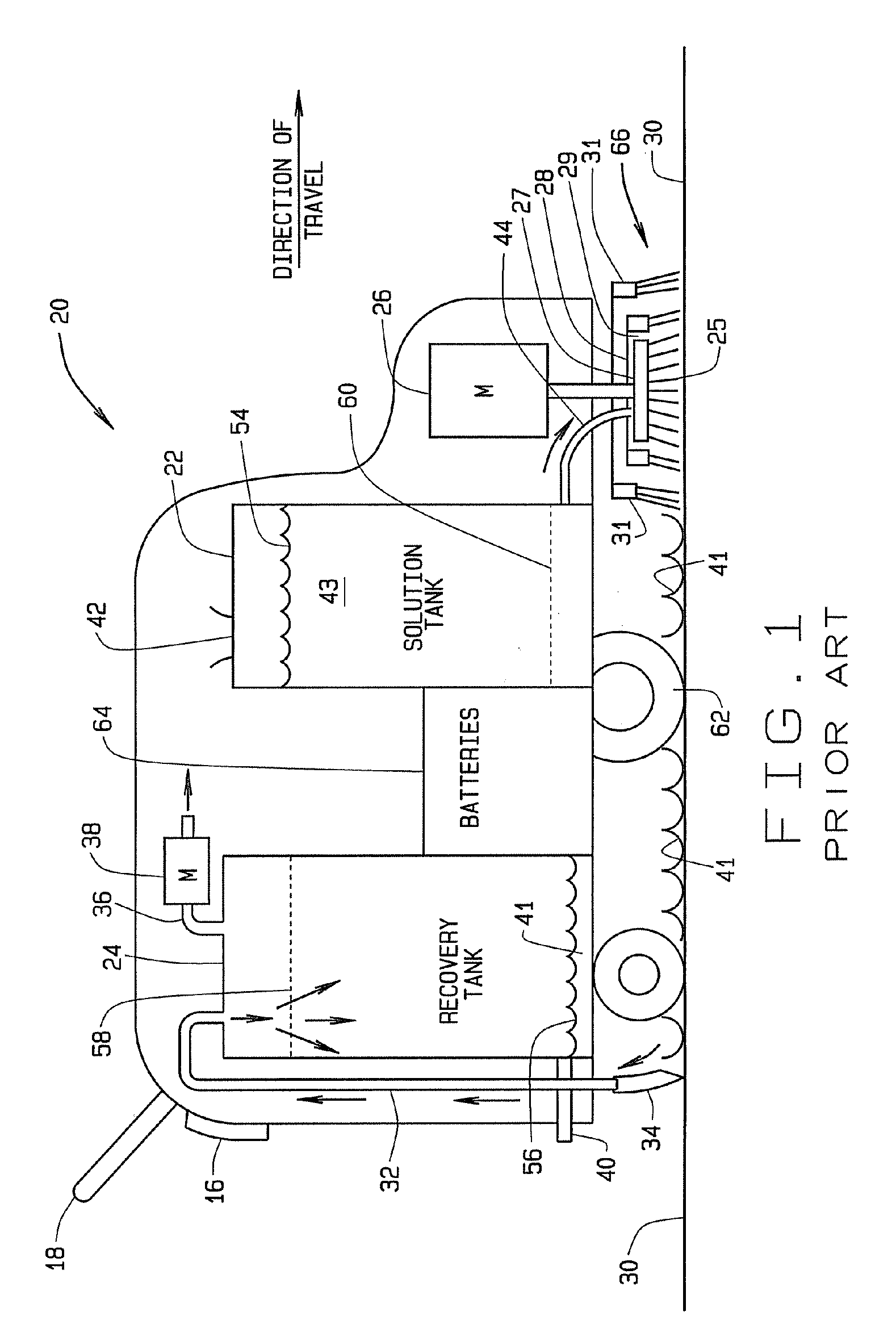
[0020]FIG. 1 is a schematic diagram of a prior art rotary motion type scrubber generally identified by the numeral 20. These scrubbers can use disc shaped brushes or cleaning pads that operate in a rotary motion about the shaft of the brush motor. These scrubbers are therefore referred to herein as rotary motion type scrubbers. Scrubbers of this type are designed to clean hard floor surfaces such as tile, linoleum, and concrete. These rotary motion scrubbers are typically used in medical facilities, office buildings, educational facilities, restaurants, convenience stores, and grocery stores.

[0021] The operator, not shown, walks behind the scrubber 20 and grips the handle 18 to control the direction of travel as indicated by the arrow at the front of the scrubber. A control panel 16 is positioned at the rear of the scrubber and has various control devices and systems well known to those skilled in the art. The control devices and systems are in electrical connection with the variou...


PUM


Abstract

This orbital motion scrubber uses less cleaning solution than many conventional rotary motion scrubbers of comparable scrub width and tank size, which results in longer solution run time. The present invention drives the cleaning element in a high speed orbital motion which results in more revolutions per spot than many conventional rotary motion scrubbers. A flexible pad driver produces better cleaning of uneven hard surface floors than some prior art designs with rigid pad drivers. The brush motor that drives the pad driver and the cleaning element of the present invention uses less electrical energy than the brush motor in many rotary motion scrubbers which results in longer battery run time.

Description

BACKGROUND OF INVENTION [0001] Rotary type scrubbers have been used for decades to clean hard floor surfaces such as tile, linoleum, and concrete. These hard floor surfaces are often uneven which presents challenges to the scrubber and may result in a floor that is not cleaned in a uniform fashion. One approach to uneven floors is a gimbaled disc shaped scrub brush. The gimbaled design allows some degree of freedom to the brush allowing it to tilt in response to the uneven floor. [0002] Another challenge to conventional floor cleaning is excess water consumption. In the past, it was a widely held belief that the more water that was applied to the floor, the cleaner it could be scrubbed. Within the last few years, this notion has fallen from favor as the floor cleaning industry has become more ecologically conscious. Various approaches have been developed by several floor equipment companies using rotary type scrubbers discussed below. [0003] One approach to the challenge of excess w...

Claims


Application Information

Patent Timeline
Patent Type & Authority Applications(United States)
IPC IPC(8): A47L11/30
CPCA47L11/305A47L11/4036A47L11/4044A47L11/4069A47L11/408
Inventor MITCHELL, KEVIN BLAINE
Owner ALTO U S
Why Eureka
Try Eureka