Lockable case

a technology of locking case and lock, which is applied in the field of locking case, can solve the problems of difficult service of conventional computers, and achieve the effect of not easily destroyed by thieves and easy operation

Inactive Publication Date: 2006-07-13
UNIVERSAL SCIENTIFIC INDUSTRIAL (SHANGHAI) CO LTD
View PDF7 Cites 18 Cited by
  • Summary
  • Abstract
  • Description
  • Claims
  • Application Information

AI Technical Summary

Benefits of technology

[0007] Therefore, the object of the present invention is to provide a lockable case having a locking assembl

Problems solved by technology

Assembly and disassembly of the housing on the frame involve the use of a tool to fasten

Method used


Image

  • Lockable case
  • Lockable case
  • Lockable case

Examples


Embodiment Construction

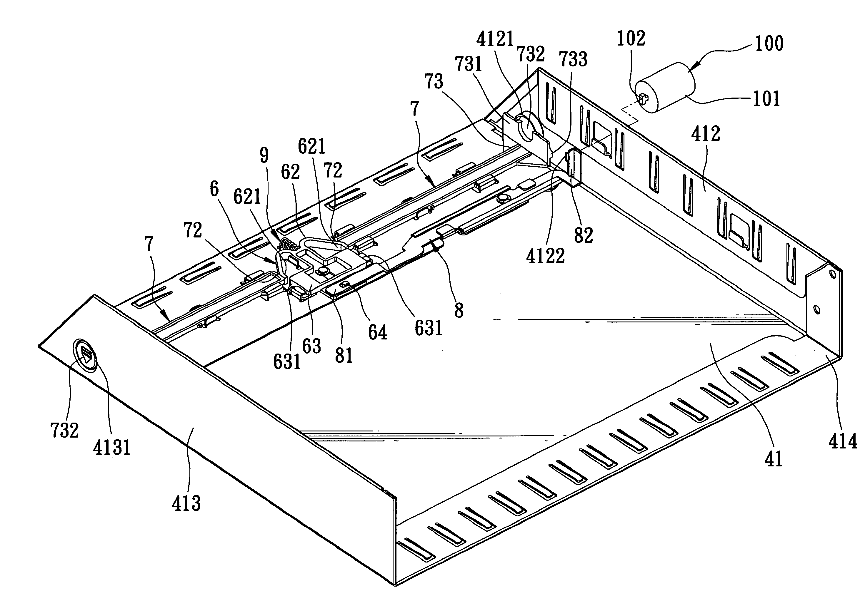
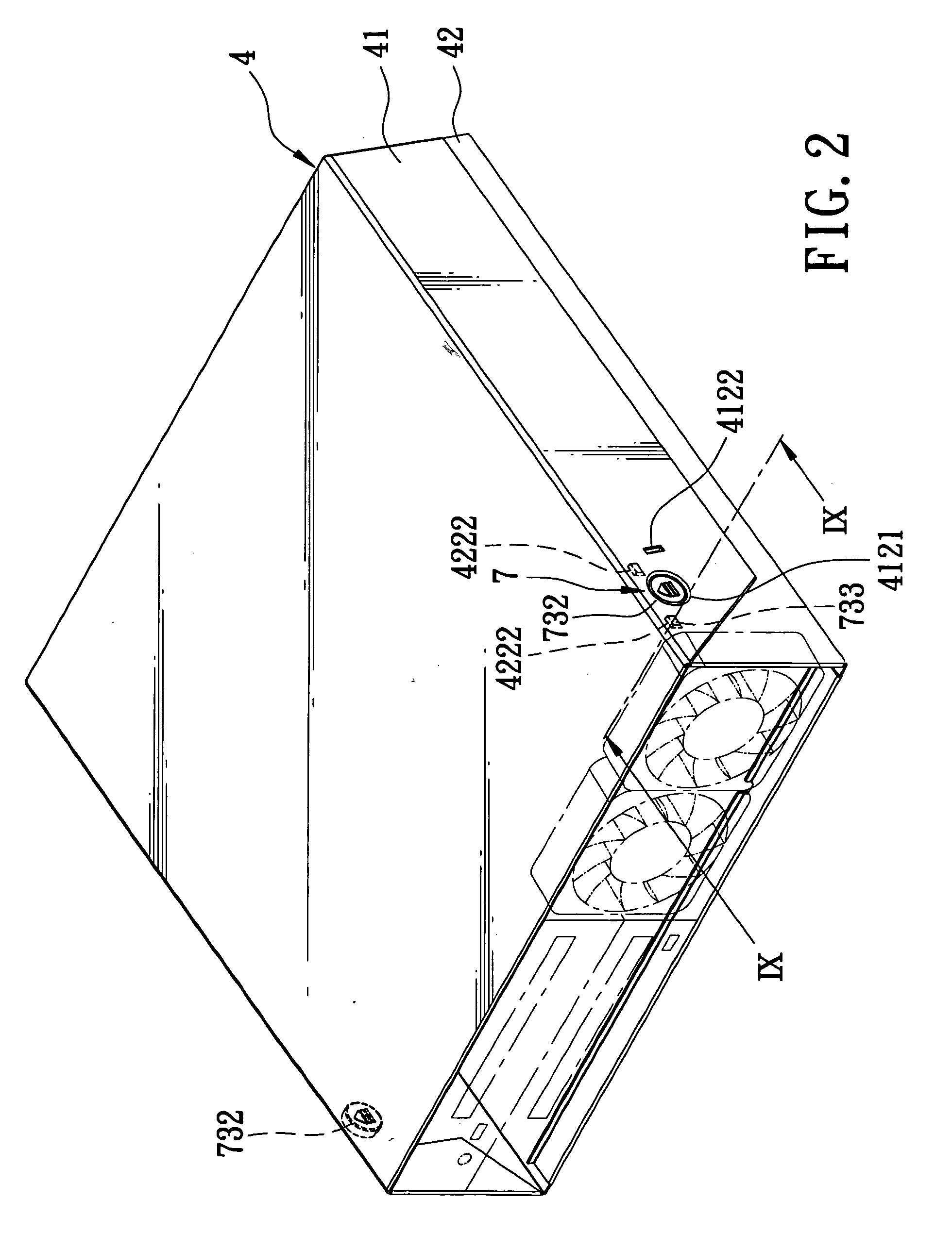
[0019] Referring to FIGS. 2 to 4, the preferred embodiment of a lockable case 4 according to the present invention is shown to comprise a top cover 41, a base casing 42, and a locking assembly. The lockable case 4 in this embodiment is a computer case.

[0020] The top cover 41 includes two opposite second lateral walls 412, 413 extending downwardly and respectively from two opposite ends of the top cover 41, and front and rear end portions 414, 415. Each of the second lateral walls 412, 413 has a through hole 4121, 4131. The second lateral wall 412 further has a rectangular lock hole 4122 proximate to the through hole 4121.

[0021] The base casing 42 includes two opposite first lateral walls 422 extending upwardly and respectively from two opposite ends of the base casing 42. The second lateral walls 412, 413 overlap the first lateral walls 422 when the top cover 41 is in a closing position relative to the base casing 42. Each of the first lateral walls 422 has a substantially U-shape...


PUM


Abstract

A lockable case includes a base casing having two opposite first lateral walls, a top cover openably connected to the base casing, a slide block, and two slide bars disposed respectively on two opposite sides of the slide block. Each slide bar has an inner end, and a locking element to engage a corresponding first lateral wall. The slide block is disposed between the inner ends of the slide bars, and is movable between locking and unlocking positions that respectively prevents and permits inward movement of the slide bars. An actuating lever is connected pivotally to the slide block to move the slide block to the locking position. An elastic member is provided for biasing the slide block toward the unlocking position.

Description

BACKGROUND OF THE INVENTION [0001] 1. Field of the Invention [0002] The invention relates to a lockable case for a computer or other devices. [0003] 2. Description of the Related Art [0004] A housing of a conventional computer is generally fastened to a frame of the computer by means of a plurality of screws. Assembly and disassembly of the housing on the frame involve the use of a tool to fasten and loosen the screws, thereby making it difficult to service the conventional computer. [0005] Referring to FIG. 1, another conventional computer is shown to include a frame 1, and a housing 2 mounted on the frame 1. The housing 2 includes a side plate 21 having a hole 22, and a locking device 3 disposed in the hole 22 and having a panel 31 which can be pulled by a user so as to open the side plate 21, as illustrated by phantom lines and designated by numeral 21′. Opening of the side plate 21 permits access to the frame 1. [0006] Although the locking device 3 can achieve its intended purpo...

Claims


Application Information

Patent Timeline
IPC IPC(8): E05B73/00B65D55/14
CPCE05B17/2038E05B65/006E05C1/10G06F1/181Y10T70/5009Y10T70/5279Y10T70/5566Y10T70/7531Y10T292/0976
Inventor CHANG, YUN-YILIN, CHIEN-TALIU, KUO-KUANG
Owner UNIVERSAL SCIENTIFIC INDUSTRIAL (SHANGHAI) CO LTD
Why Eureka
Try Eureka