Locking/release device

a technology of locking/releasing device and locking/release device, which is applied in the direction of hand carts, braking systems, braking element arrangements, etc., can solve the problems of laborious and awkward actuation of the devices described above, and achieve the effect of reducing or at least reducing the drawback suffered by known users

Inactive Publication Date: 2006-07-13
LINGLESINA BABY
View PDF2 Cites 25 Cited by
  • Summary
  • Abstract
  • Description
  • Claims
  • Application Information

AI Technical Summary

Benefits of technology

[0008] The aim of the present invention is to provide a locking / release device that is capable of eliminating or at least reducing significantly the drawback suffered by known devices.

Problems solved by technology

It is evident that actuation of the devices described above is very awkward and laborious.

Method used


Image

  • Locking/release device
  • Locking/release device
  • Locking/release device

Examples


Embodiment Construction

[0021] In the examples of embodiments that follow, individual characteristics, given in relation to specific examples, may actually be interchanged with other different characteristics that exist in other examples of embodiments.

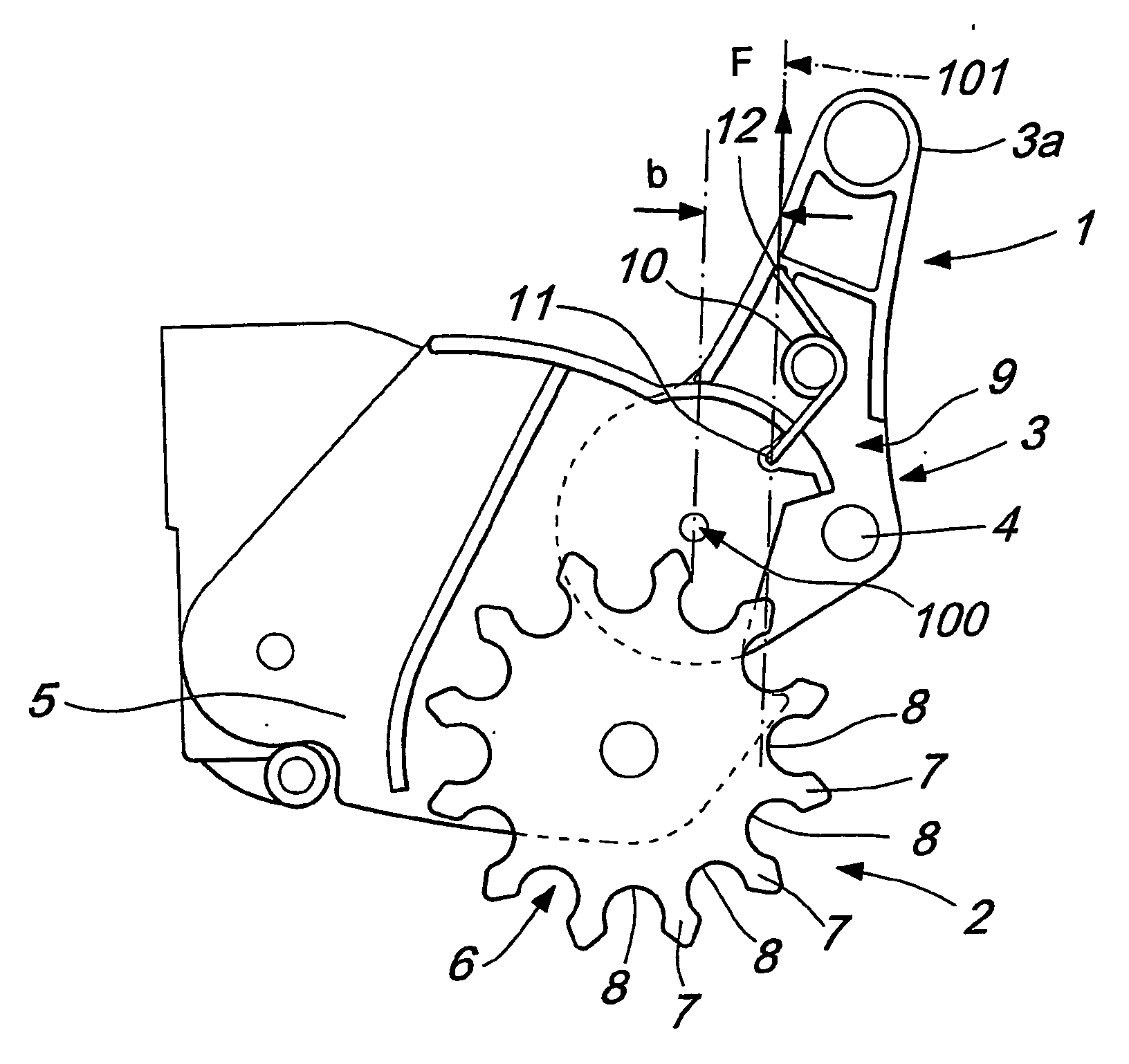
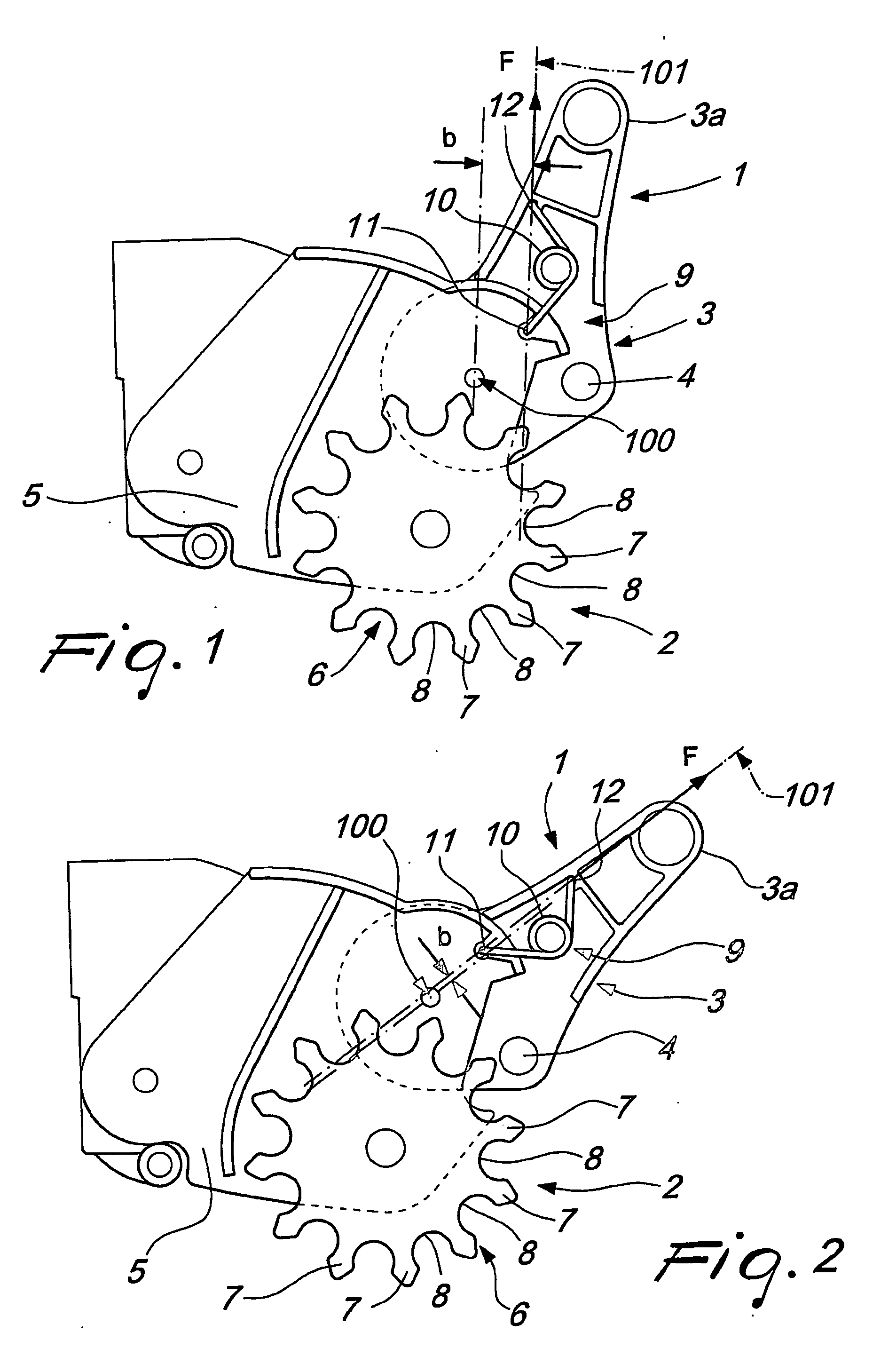
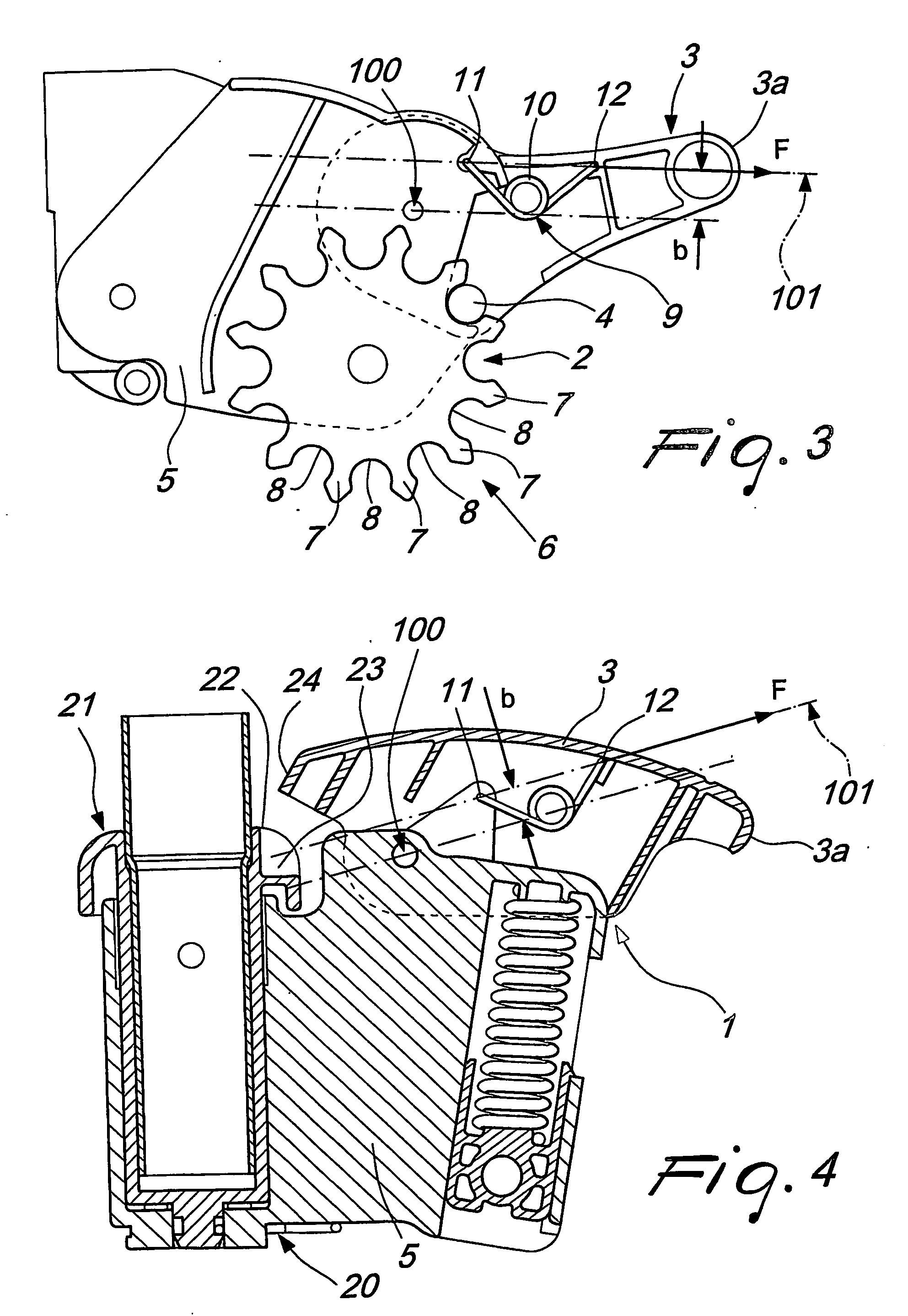
[0022] With reference to FIGS. 1 to 3, a locking / release device, generally designated by the reference numeral 1, according to the invention, can be associated with a braking device or brake 2.

[0023] Such locking / release device is constituted by an actuation lever system 3 that supports engagement means such as for example a pin 4.

[0024] The actuation lever system 3 is articulated to a supporting structure 5, which in turn supports the wheel or wheels, provided with at least one locking element rotationally rigidly coupled thereon; said locking element is accordingly movable with respect to the supporting structure 5.

[0025] In the example shown in FIGS. 1-3, the locking element is constituted by a braking ring 6.

[0026] The braking ring 6 (and more gener...


PUM


Abstract

A locking/release device particularly for pushchairs, prams or the like, comprising an actuation lever system supporting an engagement device and articulated to a supporting structure movable with respect to a locking element, having one abutment region and at least one engagement seat; the actuation lever system is mounted rotatable about a pivoting axis to pass from a release position, to a locking position of the locking element; in an abutment position, the engagement device abuts against at least one portion of the abutment region. An elastic loading element of the device acts between a first coupling portion of the supporting structure and the actuation lever system.

Description

TECHNICAL FIELD [0001] The present invention relates to a locking / release device particularly suitable for pushchairs and prams for young children. BACKGROUND ART [0002] During normal use of pushchairs and prams it is necessary to allow the user (by using locking / release devices constituted for example by actuation lever systems) to simply and effectively lock devices supported by the wheels, such as for example braking devices or castering devices (i.e., capable of ensuring or preventing castering motion of the wheel or set of wheels in the case of twin wheels). [0003] Currently, devices used to lock rotation of the wheels about their own axis (braking devices) or used to prevent castering motion are generally constituted by an actuation lever that is normally pivoted to a supporting structure of the wheel or set of wheels, which supports an engagement pin that is designed to engage, if the user acts on such lever, within a seat formed on a ring that is rigidly coupled to the wheel...

Claims


Application Information

Patent Timeline
Patent Type & Authority Applications(United States)
IPC IPC(8): B60T1/00B62B5/04B62B9/08
CPCB62B5/0461B62B9/08B62B2301/0463B62B9/082B62B9/087
Inventor TOMASI, IVANGORZA, ROBERTO
Owner LINGLESINA BABY
Why Eureka
Try Eureka