Control of RH conditions in electrochemical conversion assembly

a technology of electrochemical conversion and control conditions, applied in the field of electrochemical conversion cells, can solve the problem that the voltage provided by a single cell unit is typically too small for useful applications, and achieve the effect of reducing, eliminating, or reducing excessive humidity in the flowfield portions

Inactive Publication Date: 2006-07-13
GM GLOBAL TECH OPERATIONS LLC
View PDF3 Cites 15 Cited by
  • Summary
  • Abstract
  • Description
  • Claims
  • Application Information

AI Technical Summary

Benefits of technology

[0002] The present invention is directed to addressing performance issues attributable to membrane electrode assemblies, and the components thereof, in electrochemical conversion cells. Generally, electrochemical conversion assemblies according to the present invention can be operated without the presence of liquid water in particular flowfield portions of the assemblies and, as a result, the deleterious effects often attributable to the presence of water in fuel cell structures

Problems solved by technology

The voltage provided by a single cell unit i

Method used


Image

  • Control of RH conditions in electrochemical conversion assembly
  • Control of RH conditions in electrochemical conversion assembly
  • Control of RH conditions in electrochemical conversion assembly

Examples


Embodiment Construction

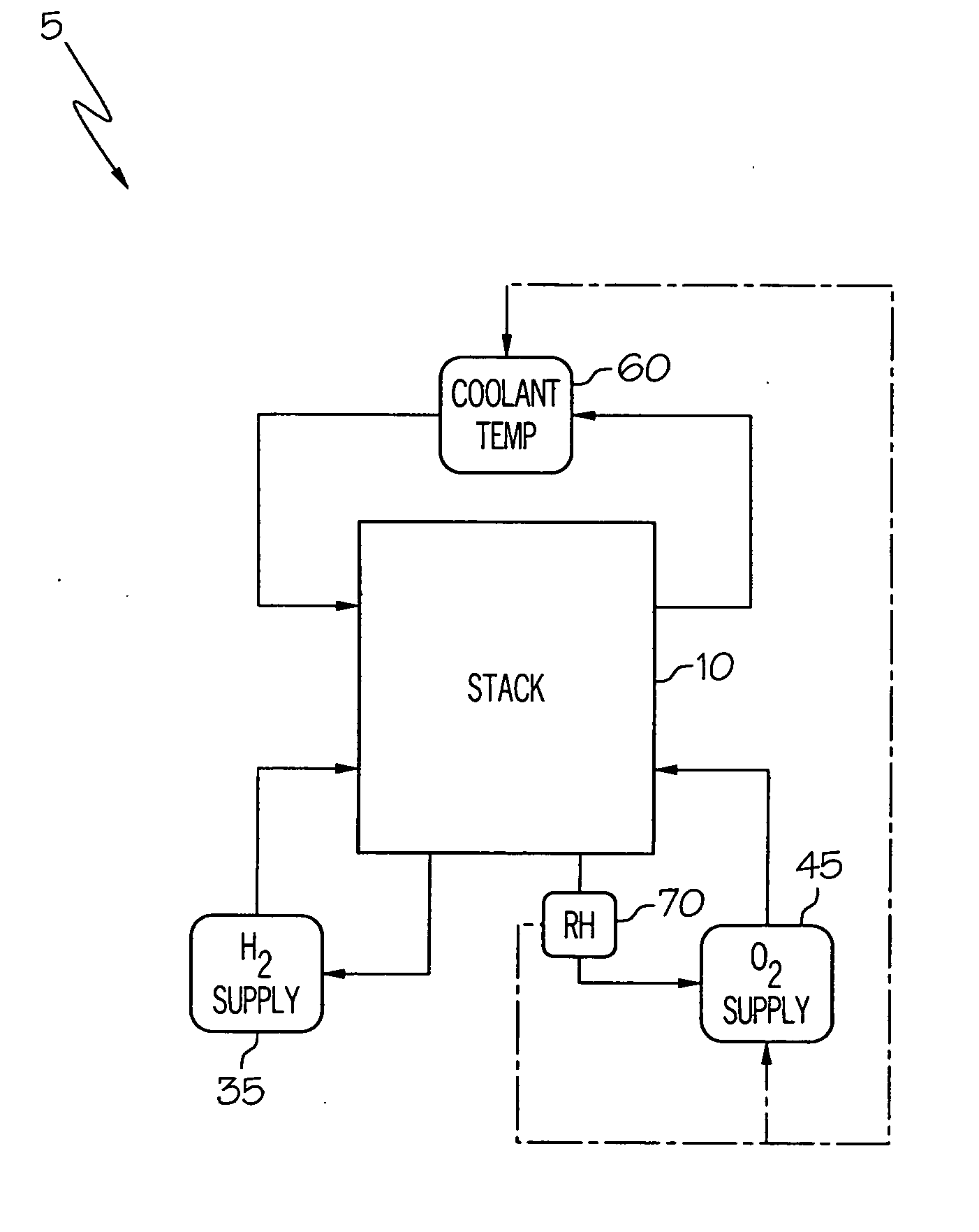
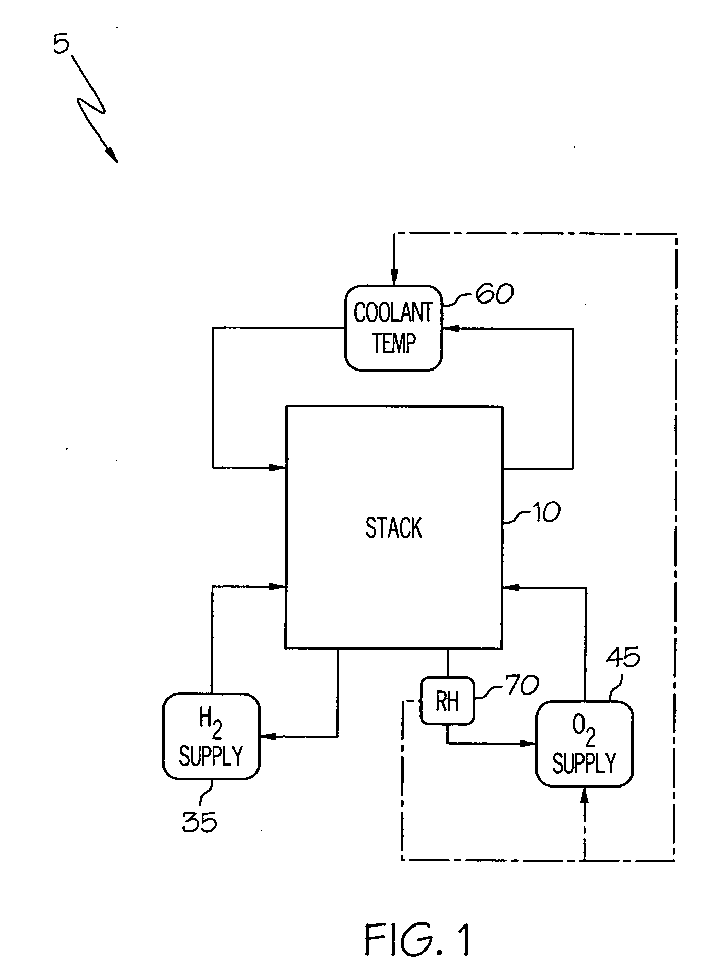
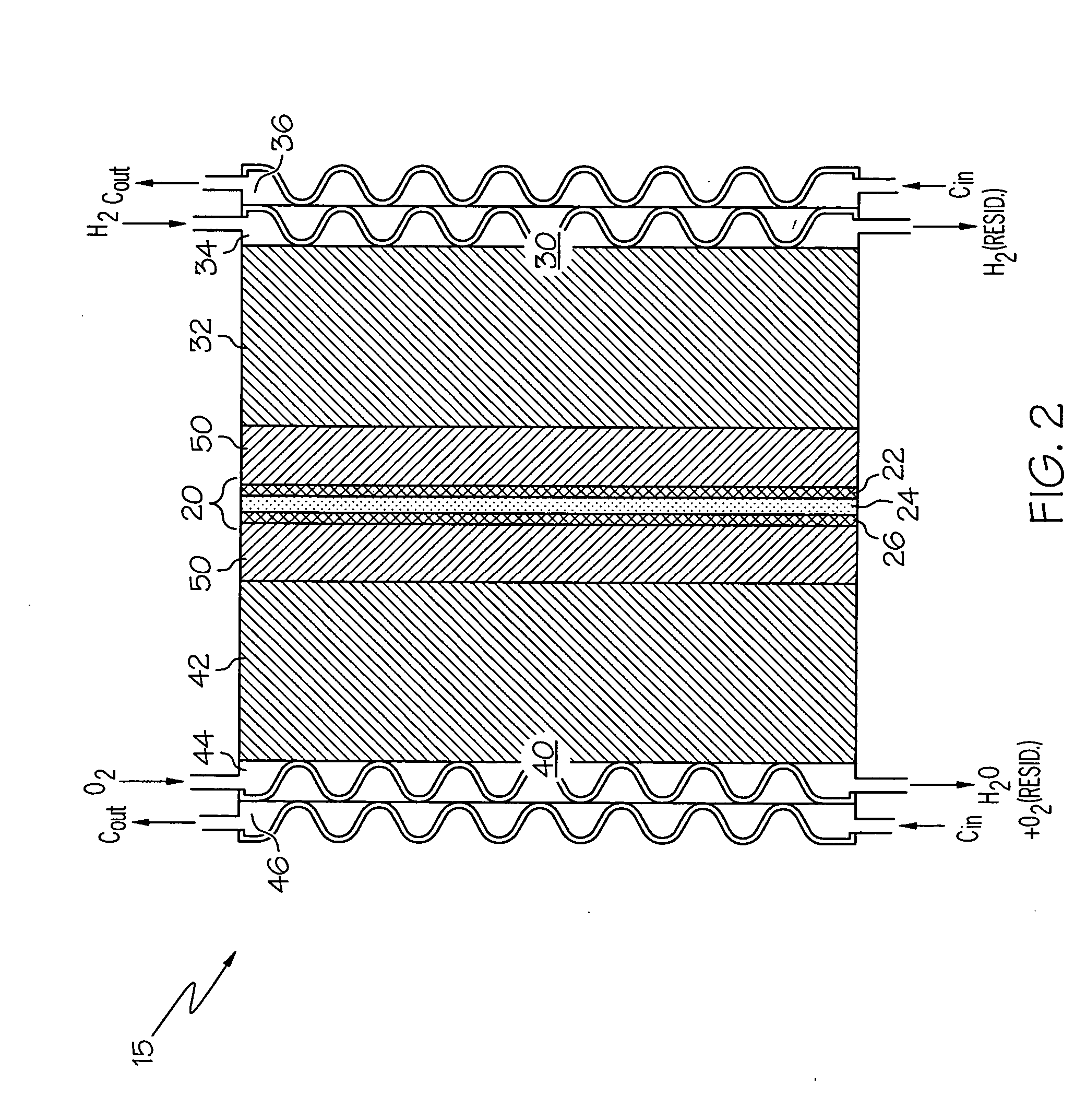
[0011] Referring to FIGS. 1 and 2, as will be appreciated by those familiar with fuel cell system and fuel cell stack design, fuel cell systems 5 typically comprise a plurality of electrochemical conversion cells 15 arranged or “stacked” to form an electrochemical conversion assembly 10. For the purposes of describing and defining the present invention, it is noted that many of the components and functional features illustrated in FIGS. 1 and 2 are presented by way of example and not limitation, and merely relate to the general construction and operation of fuel cell systems. As such, the particulars of many components illustrated in FIGS. 1 and 2 are beyond the scope of the present invention and may be gleaned from any suitable source covering such systems.

[0012] For example, referring to the electrochemical conversion cell 15 illustrated in FIG. 2, the cell 15 is configured to convert first and second reactants R1, R2, to electrical energy. The illustrated cell 15 comprises a mem...


PUM


Abstract

A system and method for controlling an electrochemical conversion assembly are provided. The system is configured such that operation of one or both of the second reactant supply and the temperature controller responds to the cathode-side RH signal to a degree sufficient to maintain relative humidity within the second flowfield portion within a suitable humidification range. The suitable humidification range is a function of the degree to which the vapor barrier layers inhibit the migration of water molecules from the membrane electrode assembly.

Description

BACKGROUND OF THE INVENTION [0001] The present invention relates to electrochemical conversion cells, commonly referred to as fuel cells, which produce electrical energy by processing first and second reactants, e.g., through oxidation and reduction of hydrogen and oxygen. By way of illustration and not limitation, a typical cell comprises a membrane electrode assembly positioned between a pair of gas diffusion media layers. A cathode flowfield plate and an anode flowfield plate are positioned on opposite sides of the cell unit, adjacent the gas diffusion media layers. The voltage provided by a single cell unit is typically too small for useful application. Accordingly, a plurality of cells are typically arranged and connected consecutively in a “stack” to increase the electrical output of the electrochemical conversion assembly or fuel cell. BRIEF SUMMARY OF THE INVENTION [0002] The present invention is directed to addressing performance issues attributable to membrane electrode as...

Claims


Application Information

Patent Timeline
IPC IPC(8): H01M8/04
CPCH01M8/04007H01M8/04119H01M2008/1095H01M2250/20Y02E60/50Y02T90/32Y02T90/40
Inventor FOWLER, SITIMA R.MUELLER, BERND
Owner GM GLOBAL TECH OPERATIONS LLC
Why Eureka
Try Eureka