
Ligature device

a technology for ligatures and orthodontics, applied in the field of ligature devices for orthodontics, can solve the problems of serious biological damage to patients, general tendency to oversize the elastic load applied to the wire, and partially consumed elastic energy accumulated in the wire, etc., and achieve the effect of reducing or eliminating the above inconveniences

Inactive Publication Date: 2008-02-07
LEONE SPA
View PDF1 Cites 14 Cited by
  • Summary
  • Abstract
  • Description
  • Claims
  • Application Information

AI Technical Summary

Benefits of technology

[0008] The present invention aims at eliminating or at least at reducing the above inconveniences.
[0009] These results have been achieved, according to the present invention, by a device having the features described in claim 1. Further features of the present invention are the subject of the dependent claims. Thanks to the present invention it is possible to guarantee an improved possibility of movement of the preformed wire both in the mesodistal direction and by flexion, outside the bracket wings, without modifying the shape or the nature of the preformed wire or of the orthodontic bracket. Therefore, the elastic overload of the wire during its pre-forming phase can be eliminated or considerably reduced, so as to allow a more correct application of the corrective forces on the interested teeth. Moreover, the binding or ligature device according to the present invention allows a remarkable reduction of the orthodontic treatment time, is easy to build, economic, comfortable for the patient, easy to use and reliable, even after a relatively long working time.

Problems solved by technology

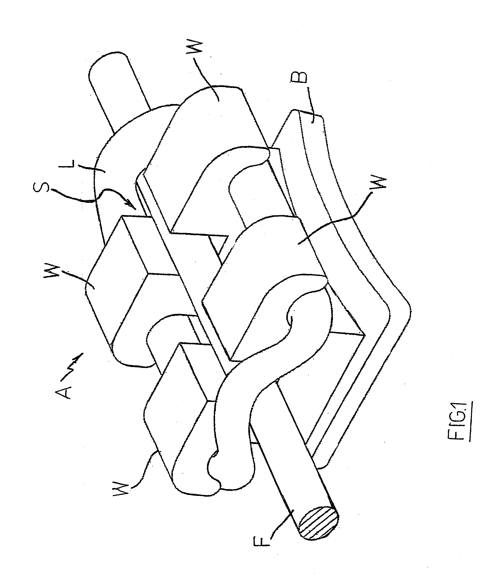
However, as in the above ligature systems the movements of the preformed wire, which tends to assume its original form, generate remarkable friction due to the contact between the wire itself and the ligature rings mounted on each orthodontic bracket, the elastic energy accumulated in the wire is partially consumed to eliminate friction, so there is a general tendency to oversize the elastic load applied to the wire during the preforming phase.
This may lead to serious biological damages for the patient and compels the odontologist to examine him frequently.
A drawback of the above-mentioned ligature lies in that it is quite complex from a structural and manufacturing point of view and, consequently, it is quite expensive.
Obviously, the stretching step is to be carried out with the bracket being applied to the respective tooth but, in relation the very small dimensions of both the bracket and the ligature, the stretching step results in a quite complex operation for the odontologist.
Consequently, the cement applied between the tot and the bracket base may be subject to weakening.
Furthermore, the bracket may be subject to displacement.

Method used


Image

  • Ligature device
  • Ligature device
  • Ligature device

Examples


Embodiment Construction

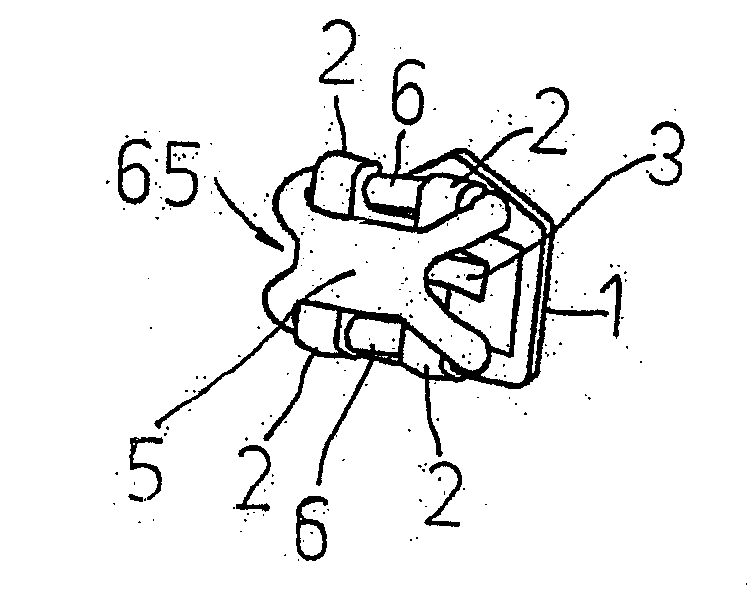
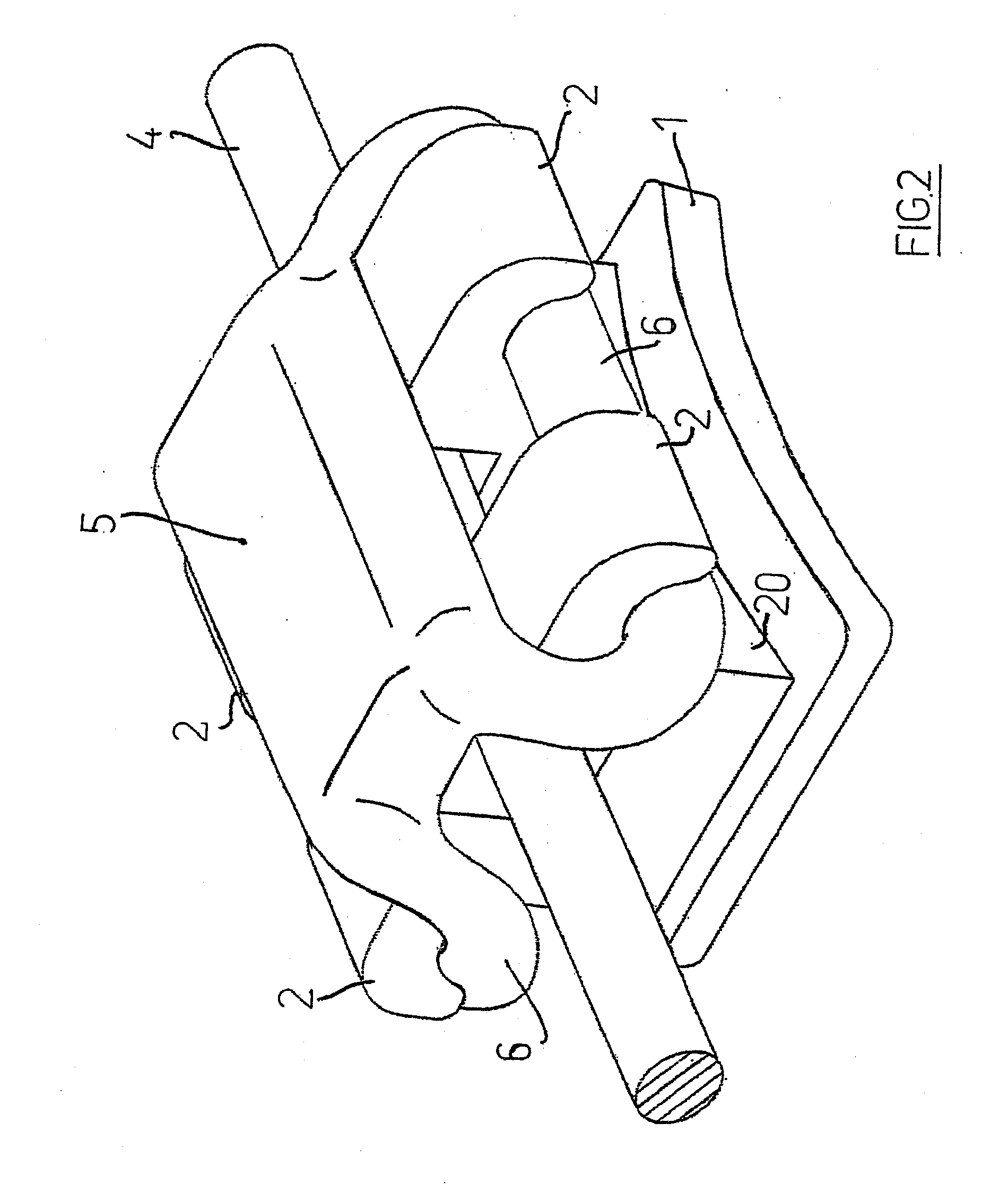
[0021] According to FIGS. 2-5 of the enclosed drawings, a ligature device for orthodontic brackets according to the present invention is designed to be mounted on any orthodontic bracket available on the market, that is to say an orthodontic bracket comprising a base (1) with a surface (10) to be cemented on the vestibular face of a tooth and more wings defined by a body (20) which emerges from the base (1) on the side opposite to that of the surface (10). Wings (2) extend in the occlusal gingival direction, while a slot (3) extends between them in the mesodistal direction, so as to allow the passage of a corresponding arch portion of a preformed wire (4). Moreover, each of the wings (2) features a lower surface, that is to say a surface (21) which is turned toward the base (1) of the orthodontic bracket so that the ligature device can be coupled with it, as described in detail below.

[0022] The wire (4) can be of any kind available on the market.

[0023] A ligature device according ...


PUM


Abstract

Ligature device for orthodontic brackets, consisting of an elastic body with a central portion (5) and two lateral rings (6) positioned on two mesodistal sides of the central portion (5), on opposite sides with respect to the latter, the rings being intended to be stretched to be coupled with the wings (2) of an orthodontic bracket so that the central portion (5) results above the same bracket wings (2), characterized in that the lateral rings (6) form at least a curve (65) corresponding to a mesodistal side of the orthodontic bracket at the height of the wings (2), the vertex of the at least one curve (65) being turned toward the orthodontic bracket, that is to say toward the central portion (5) of the ligature device, the length (a) of each of the rings (6) exceeding the length (c) of the central portion (5) both when the rings (6) are stretched and un-stretched, so that the value of the ratio (a) / (c) is less than one in both the stretched and un-stretched configurations.

Description

CROSS REFERENCE TO RELATED APPLICATION [0001] This application is a continuation application under 37 CFR 1.53(b) of pending prior application number 11 / 116,583 filed Apr. 28, 2005.FIELD OF THE INVENTION [0002] The present invention relates to a ligature device for orthodontics. BACKGROUND OF THE INVENTION [0003] Orthodontic procedures, in which a plurality of orthodontic brackets are used, have widely been adopted for a long time. Each orthodontic bracket is cemented on the vestibular face of a tooth which belongs to a dental arch under treatment. Along each dental arch, a suitably preformed wire arch passes through the orthodontic brackets. On this purpose, each orthodontic bracket features a slot extending in the mesodistal direction, in which the above wire passes, as well as a retention base. The slot is positioned between two couples of wings emerging from said base which extend in the occlusal gingival direction, between which an elastic ring commonly said “binding” or “ligat...

Claims


Application Information

Patent Timeline
IPC IPC(8): A61C7/30
CPCA61C7/303
Inventor SCOMMEGNA, GABRIELEDOLFI, MAURIZIO
Owner LEONE SPA
Learn More