Hanging cable shortener arrangement

a technology of hanging cables and shorteners, which is applied in the field of hanging cable shorteners, can solve the problems of inability to the inability to cut the inability to accurately adjust the height of the cable or line, so as to achieve the effect of being easily adjusted

Inactive Publication Date: 2006-07-13
VISUAL CREATIONS INC
View PDF8 Cites 11 Cited by
  • Summary
  • Abstract
  • Description
  • Claims
  • Application Information

AI Technical Summary

Benefits of technology

[0018] The generally rigid peripheral lip of a curvilinear flange on one end of the hub is spaced apart a certain distance from the rigid peripheral lip on the curvilinear flange on the other end of the hub. The certain spaced-apart distance of the peripheral lips is preferably greater than the diameter of the cable (line, drawn plastic filament or wire or the like) being utilized to support a sign from the overhead support or ceiling. The certain spaced-apart distance of the peripheral lips is critically less than the two cable diameters, so as to prevent unintended wrapping (or more likely unwrapping) of the cable past itself in the gap, that is, the certain spaced-apart distance between the opposed peripheral lips of the flanges. It would t

Problems solved by technology

Replacing these cables or lines, cutting them or crimping loops onto the end can be an expensive and inaccurate way to accomplish such height adjustment.
These mechanisms, however, appear unduly complicated and hence more expensive and undesirable for large use thereof and more likely to be utilized incorrectly.
This makes the system somewhat expensive.
This is a somewhat sophisticated device which would not provide a strong griping tension for supporting a sign nor be able to support any appreciable weight due to the flexible nature of the material.
This apparatus is overly complex, highly visible, and would result in kinking of the cable.
Any release of pressure in the cables (such as the sign being bumped or otherwise being

Method used


Image

  • Hanging cable shortener arrangement
  • Hanging cable shortener arrangement
  • Hanging cable shortener arrangement

Examples


Embodiment Construction

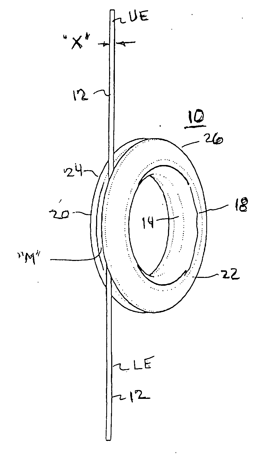
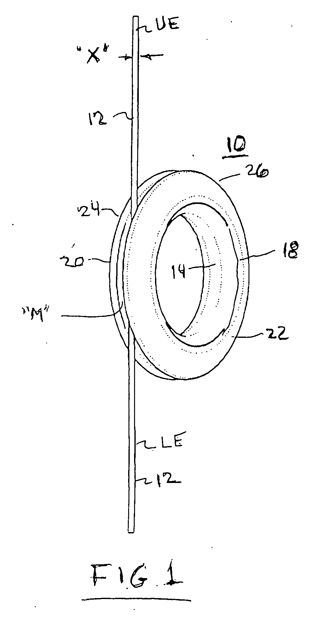
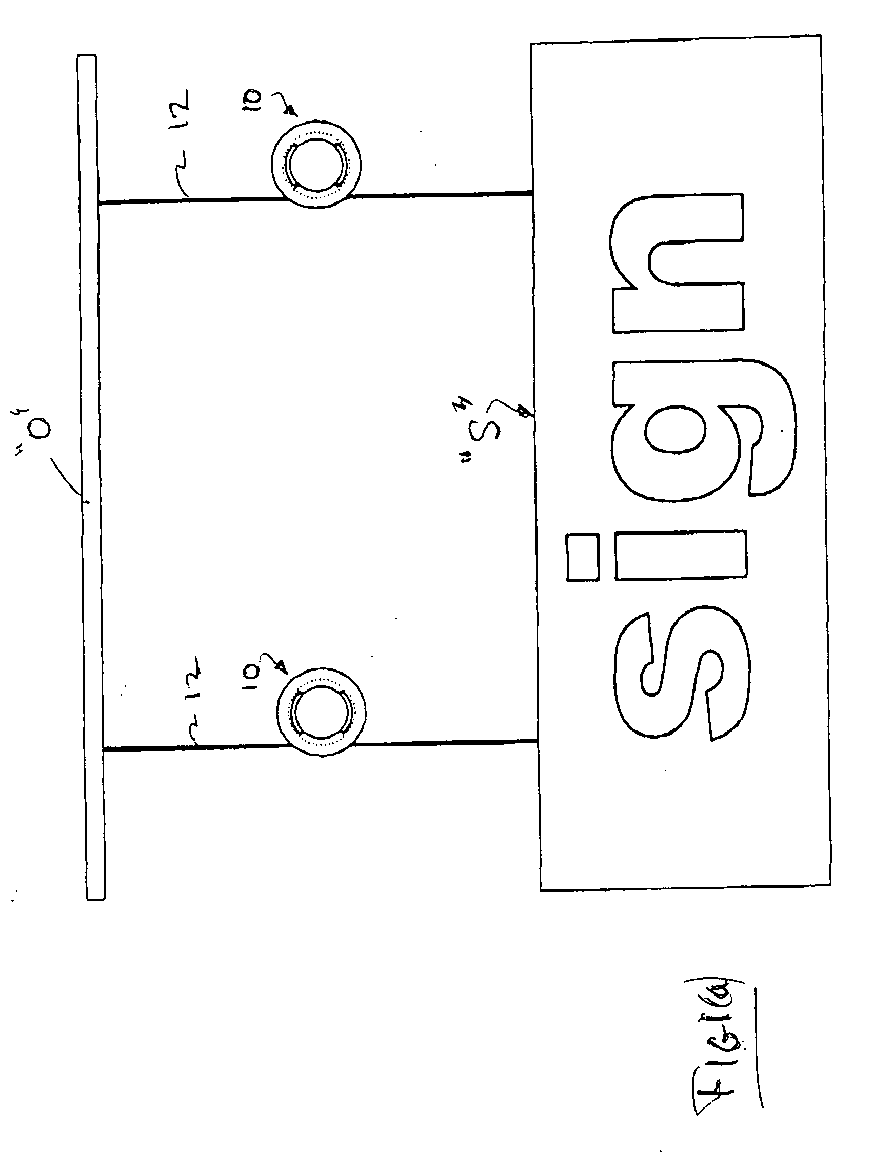
[0046] Referring now to the drawings in detail, and particularly to FIGS. 1 and 1(a), there is shown the present invention which comprises a sign cable shortener apparatus 10 for hanging signs “S” and displays from an overhead support “O”, as shown in FIG. 1a, such support comprising a ceiling, beam or the like. A non-compressable cable 12 having an upper end UE would be attached to a ceiling or overhead support “O”, and the lower end LE of the cable 12 would be 180 degrees out of phase with the upper end UE of the cable 12, and attached to the sign to be supported from that ceiling or overhead support. One or more wraps of cable would be taken (or untaken) around the cable shortener as described hereinbelow, to shorten or lengthen that cable 12 as necessary.

[0047] The cable shortener apparatus 10 of the present invention as embodied in FIG. 1 thus comprises, after assembly, a rigid annular hub 14 of fixed axial length, having a pair of ends 16 and 18. A generally rigid annularly-s...


PUM


Abstract

A cable shortener apparatus for permitting the length adjustment of a cable having a certain incompressable diameter. The cable is arranged for supporting a sign carrier from an overhead support. The cable shortener apparatus may be comprised of a duplicate pair of generally rigid annular rings lockably engagable with one another. Each ring may have an inner arcuate hub flange which defines a fixed hub surface for receiving at least one wrap of a support cable. An annular edge on each of the rings is spaced apart from one another when the rings are mated together. The spaced apart annular edges defining a gap no wider than the diameter of the cable being wrapped about the hub of the shortener.

Description

BACKGROUND OF THE INVENTION [0001] 1. Field of the Invention [0002] This invention relates to cable or line shorteners and more particularly to cable shortener apparatus to permit the ready height adjustment of a ceiling suspended sign by said shortener apparatus arranged at a mid-point of said suspended cable, and is a continuation-in-part application of co-pending, commonly assigned U.S. patent application Ser. No. 10 / 037,314, and U.S. patent application Ser. No. 10 / 036,756, which are each incorporated herein by reference in their entirety. [0003] 2. Prior Art [0004] Retail commercial establishments often display signs and banners suspended from a ceiling by one or more cables or lines. Often the length of these cables or lines need to be changed depending upon the size of the sign or the height of the ceiling. Replacing these cables or lines, cutting them or crimping loops onto the end can be an expensive and inaccurate way to accomplish such height adjustment. [0005] A number of...

Claims


Application Information

Patent Timeline
IPC IPC(8): B65H75/40
CPCB65H75/143B65H75/22B65H75/406B65H75/2227B65H75/2281
Inventor PITCHER, DAVID
Owner VISUAL CREATIONS INC
Why Eureka
Try Eureka